 Email: jiedong@sxrszdh.com
 Phone / Wechat:+86 15340683922
Description
Product Introduction (Anti-Template)
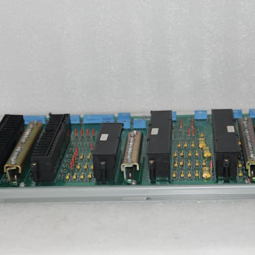
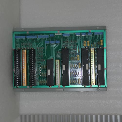
Terminal block numbering that doesn’t match your wiring diagram is a headache you don’t need during a plant outage. The DS3800NRTB is GE’s digital output termination board with an alternative terminal block layout compared to the standard NRTA. The NRTB has the same 32-channel output capability, same 0.5A per channel current rating, and same flyback diode protection—but the terminal block arrangement is different, which might match your existing cabinet wiring better.
What you get is identical electrical performance to the NRTA, but with a different terminal block row arrangement. The NRTB groups channels differently on the top and bottom rows—some plants prefer this layout because it matches their cable tray routing. A Midwest power plant standardized on the NRTB because the channel numbering aligned with their marshalling cabinet wiring, saving them about two hours per board installation compared to re-wiring for the NRTA. The board is electrically identical to the NRTA—only the mechanical layout differs.
Key Technical Specifications
| Parameter | Value |
|---|---|
| Product Type | Digital output termination board |
| Board Form Factor | Full-height 6U PCB |
| Output Channels | 32 digital output channels |
| Output Voltage | 24V DC nominal (module-dependent) |
| Output Current per Channel | 0.5A continuous, 1.0A peak (inductive) |
| Total Board Current | 8A maximum (all channels combined) |
| Output Type | Determined by output module (sourcing/sinking) |
| Protection | Flyback diode per channel (inductive load protection) |
| Short-Circuit Protection | Via I/O module (not on termination board) |
| Voltage Drop | <0.5V at 0.5A per channel |
| LED Indicators | Green (output ON), Off (output OFF) |
| Terminal Block Type | Screw-clamp, accepts 14-22 AWG wire |
| Terminal Block Layout | Top row: channels 1-16, Bottom row: channels 17-32 (different grouping than NRTA) |
| Connector Type | 50-pin header to digital output module |
| PCB Material | FR-4, standard Tg 135°C |
| PCB Layers | 6-layer |
| Operating Temp | 0°C to +55°C |
| Board Thickness | 1.6mm |
| Weight | 0.7 kg (approx. 1.5 lbs) |
| Mounting | Screws to rack chassis (hardware not included) |
Compatible Replacement Models
| Model | Compatibility | Notes |
|---|---|---|
| DS3800NRTB | ✅ Drop-in Replacement | Exact match. Direct swap with no wiring changes if your existing board is an NRTB. |
| DS3800NRTA | ⚠️ Hardware Difference | Standard terminal block layout (NRTA) is different from the NRTB. If you’re swapping an NRTA for an NRTB, you’ll need to re-terminate your field wiring. Labor: ~2-3 hours. |
| DS3800NRTB-1 | ⚠️ Software Compatible | Older revision with lower current rating (0.2A per channel). Verify your load requirements. Labor: ~2 hours. |
| DS3800NRTC | ⚠️ Hardware Difference | 48V DC version. Not compatible with 24V systems. |
| IS200ERTA (Mark V) | ❌ Hardware Incompatible | Mark V board with different connector pinout. Not compatible. |
Frequently Asked Questions (FAQ)
What’s the actual difference between the NRTB and the NRTA?
The electrical design is identical—both boards have 32 channels, 0.5A per channel, flyback diode protection, and LED status. The difference is entirely in the terminal block layout. The NRTA has a standard terminal arrangement; the NRTB has an alternative arrangement that groups channels differently on the top and bottom rows. If your existing wiring diagram references the NRTB, stick with it. If you’re swapping from an NRTA, you’ll need to re-terminate.
Can I swap an NRTA for an NRTB without rewiring?
No. The terminal block channel numbering is different. If you plug an NRTB into a rack that was wired for an NRTA, channel 1 on the NRTB might be channel 17 on the NRTA—your outputs won’t map correctly. You’d need to re-terminate all 32 channels. It’s doable, but it’s a 2-3 hour job. We recommend matching the board type to your existing wiring diagram.
What’s the maximum current per channel?
0.5A continuous per channel, with 1.0A peak for inductive loads (solenoids, relays). The total board current is 8A. If you’re driving loads above 0.5A, use an external interposing relay.
Does the NRTB have flyback diode protection?
Yes, each channel has a flyback diode. That diode clamps the voltage spike from an inductive load (solenoid, relay) when it’s de-energized, protecting the output module. The diodes are surface-mount components—they’re not field-replaceable. If one fails, you need to replace the board.
What do the LED indicators show?
Green: the output is ON (the module has commanded the output ON). Off: the output is OFF. The LEDs are powered from the output side, so they work even if the I/O module is powered down—a useful diagnostic.
Can I hot-swap the NRTB?
No. The board is connected to live field loads. Pulling it while powered could cause arcing and damage the output module. Power down the rack, swap, and power back up. Don’t hot-swap.
What’s your test procedure for the NRTB?
Our inbound test:
- Visual: inspect terminal blocks, bent pins, and flyback diodes for discoloration.
- Diode check: each flyback diode must read 0.6V forward, open reverse.
- Current test: apply a 0.5A load to each output—voltage drop under 0.5V.
- Isolation: 500V DC between adjacent channels—must exceed 10MΩ.
- LED test: verify green LEDs illuminate with 24V DC applied.
We reject about 4% of inbound NRTB boards—mostly for failed flyback diodes or cracked terminal blocks.
ABB 3HAC025338-006
TRICONEX 3664
GE DS200NATOG3A
ABB SAFT112POW
 Email: sales@plcfcs.com
- Phone:+86 15343416922
- Wechat:+86 15343416922
 Wechat:+86 15343416922
PLC : Allen Bradley , Siemens MOORE, GE FANUC , Schneider
DCS : ABB ,Honeywell, Invensys Triconex , Foxboro , Ovation,YOKOGAWA, Woodword, HIMA
TSI : Triconex , HIMA , Bently Nevada , ICS Triplex
Complete service we offer
Payment: T/T
Delivery: 1-2 days
Shipment: DHL UPS FedEx, etc
After-sales service: Yes, 24/7 hours