 Email: jiedong@sxrszdh.com
 Phone / Wechat:+86 15340683922
Description
Product Introduction (Anti-Template)
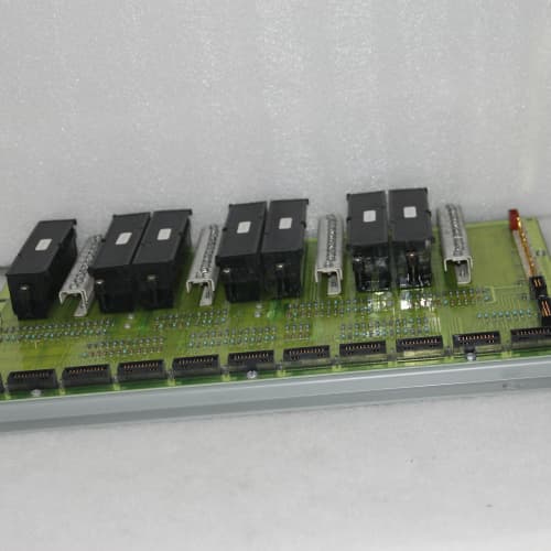
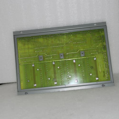
A digital output board that’s been revised half a dozen times is usually a sign GE got it right the first time. The DS3800NRTA1A1A is the base revision of GE’s digital output termination board for the Mark VIe system—and it’s been the workhorse for over a decade. The 1A1A designation indicates the original terminal block layout and base PCB material, no frills, no upgrades, just solid field-proven design.
What you get is 32 channels of 24V DC output driving capability, with flyback diode protection on every channel—the kind of protection that saves your output modules from the inductive kick of solenoid valves. Compared to later revisions (like the 1G1G which adds enhanced filtering and temperature range), the 1A1A trades extreme durability for simplicity and lower cost. It’s the board you want for a standard control room environment where you don’t need ruggedized features. A chemical plant in Texas has been running the same 1A1A boards in their control room for 12 years without a single failure—they just work.
Key Technical Specifications
| Parameter | Value |
|---|---|
| Product Type | Digital output termination board |
| Board Form Factor | Full-height 6U PCB |
| Output Channels | 32 digital output channels |
| Output Voltage | 24V DC nominal |
| Output Current per Channel | 0.5A continuous, 1.0A peak (inductive) |
| Total Board Current | 8A maximum (all channels combined) |
| Output Type | Determined by output module (sourcing/sinking) |
| Protection | Flyback diode per channel (inductive load protection) |
| Short-Circuit Protection | Via I/O module (not on termination board) |
| Voltage Drop | <0.5V at 0.5A per channel |
| LED Indicators | Green (output ON), Off (output OFF) |
| Terminal Block Type | Screw-clamp, accepts 14-22 AWG wire |
| Terminal Block Layout | 2 rows of 16 channels (top/bottom) |
| Connector Type | 50-pin header to digital output module |
| PCB Material | FR-4, standard Tg 135°C |
| PCB Layers | 6-layer |
| Operating Temp | 0°C to +55°C |
| Board Thickness | 1.6mm |
| Weight | 0.7 kg (approx. 1.5 lbs) |
| Mounting | Screws to rack chassis (hardware not included) |
Compatible Replacement Models
| Model | Compatibility | Notes |
|---|---|---|
| DS3800NRTA1A1A | ✅ Drop-in Replacement | Exact match. Base revision. Direct swap with no wiring changes. |
| DS3800NRTA (standard) | ✅ Drop-in Replacement | Same board, typically shipped without the revision suffix. The 1A1A is the base revision. |
| DS3800NRTA-1 | ⚠️ Software Compatible | Older revision with lower current rating (0.2A per channel). Verify your load requirements before swapping. Labor: ~2 hours to verify loads. |
| DS3800NRTA1G1G | ✅ Drop-in Replacement | Newer ruggedized version with enhanced filtering and temperature range. Fits the same connectors and mounting holes. Direct upgrade. |
| DS3800NRTB | ⚠️ Hardware Difference | Similar board with different terminal block layout. Verify your wiring diagram if swapping. Labor: ~1 hour. |
| DS3800NRTC | ⚠️ Hardware Difference | 48V DC version. Not compatible with 24V systems. |
| IS200ERTA (Mark V) | ❌ Hardware Incompatible | Mark V board with different connector pinout. Not compatible. |
Frequently Asked Questions (FAQ)
What’s the difference between the 1A1A and the newer versions like the 1G1G?
The 1A1A is the base revision: standard PCB material, standard terminal blocks, standard operating temperature range (0-55°C). The 1G1G adds reinforced terminal anchoring (through-hole pins), high-Tg PCB material for high temperatures, and enhanced EMI filtering. The 1A1A is perfectly adequate for standard control room environments; the 1G1G is for harsh environments (vibration, temperature extremes, high noise). The 1A1A is about 30% less expensive.
What’s the maximum current per channel on the 1A1A?
0.5A continuous per channel, with 1.0A peak for inductive loads like solenoids. The total board current is 8A—that’s the combined current across all 32 channels. If you’re driving more than 8A total, the board will overheat. For loads over 0.5A per channel (like large contactors), use an external interposing relay—the 1A1A isn’t designed for heavy loads.
Can I drive a 48V solenoid with the 1A1A?
No, the board is designed for 24V DC only. The output module determines the voltage—the 1A1A just passes the signal. If your system uses 48V, you need the NRTC version. Check your system voltage before ordering.
What is the flyback diode for, and does the 1A1A have one per channel?
Yes, the 1A1A has a flyback diode per channel. When a solenoid valve is de-energized, the collapsing magnetic field creates a high-voltage spike (100-300V) that can destroy the output module’s driver transistor. The flyback diode clamps that spike to about 1V above the supply voltage, protecting the module. It’s a critical feature for reliability when driving inductive loads.
How do I know if a flyback diode has failed?
If the diode fails, the output module will eventually fail—usually within 3-6 months if the output is cycled frequently. You can test the diode with a multimeter: measure the diode drop (0.6V forward) across the diode. If it reads open circuit in both directions, the diode is blown. The diodes are surface-mount components and not field-replaceable—you’d need to replace the whole board.
Can I hot-swap the 1A1A while the rack is powered?
No. The board is connected to live field loads (solenoids, relays). Pulling it while powered could cause arcing on the connector pins and damage the output module. Power down the rack, swap the board, and power back up. It’s a 15-minute job.
What do the LED indicators on the 1A1A mean?
- Green: output is ON (the module has commanded the output ON).
- Off: output is OFF.
The LEDs are powered from the output side, so they show the actual output state—even if the I/O module is powered down. This makes troubleshooting quick.
What’s the difference between sourcing and sinking outputs on the 1A1A?
The 1A1A is a passive board—it doesn’t care if the output is sourcing (switching positive) or sinking (switching ground). The output module determines the type. Most Mark VIe digital output modules are sourcing. The termination board just passes the current and voltage.
What’s your test procedure for the 1A1A?
Our inbound test:
- Visual: inspect terminal blocks for cracks, bent pins, and discolored components (especially the flyback diodes).
- Diode check: measure each flyback diode—must read 0.6V forward, open reverse.
- Current test: apply a 0.5A load to each output and verify the voltage drop across the terminal is under 0.5V.
- Isolation: 500V DC between adjacent channels—must exceed 10MΩ.
- LED test: apply 24V DC to the input and verify the LED illuminates.
We reject about 4% of inbound 1A1A boards—mostly for failed flyback diodes or cracked terminal blocks. The flyback diodes are the most sensitive component.
What’s the most common field issue with the 1A1A?
Overtightening the terminal screws. The terminal blocks can crack if you torque beyond 0.5 Nm. A cracked terminal block causes intermittent connections. Use a torque screwdriver. The second most common issue is a failed flyback diode from a solenoid that draws more than 0.5A—oversized solenoids will overheat the diodes. Check your solenoid data sheets. Also, the 1A1A has no surge protection beyond the flyback diodes—if you’re in a lightning-prone area, add external surge suppressors on the field wiring.
SIEMENS 1P6RA7031-6DS22-0
ABB CI855
SCHNEIDER BMEP585040
A-B 2711P-T12C4A8
 Email: sales@plcfcs.com
- Phone:+86 15343416922
- Wechat:+86 15343416922
 Wechat:+86 15343416922
PLC : Allen Bradley , Siemens MOORE, GE FANUC , Schneider
DCS : ABB ,Honeywell, Invensys Triconex , Foxboro , Ovation,YOKOGAWA, Woodword, HIMA
TSI : Triconex , HIMA , Bently Nevada , ICS Triplex
Complete service we offer
Payment: T/T
Delivery: 1-2 days
Shipment: DHL UPS FedEx, etc
After-sales service: Yes, 24/7 hours