 Email: jiedong@sxrszdh.com
 Phone / Wechat:+86 15340683922
Description
Product Introduction (Anti-Template)
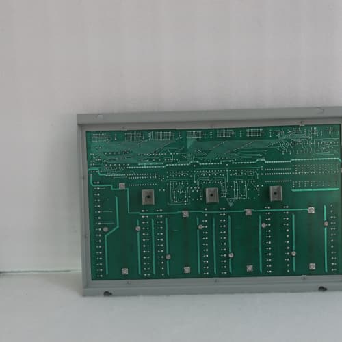
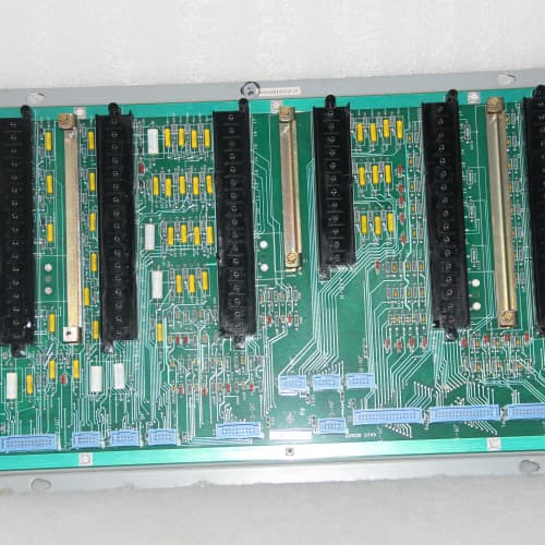
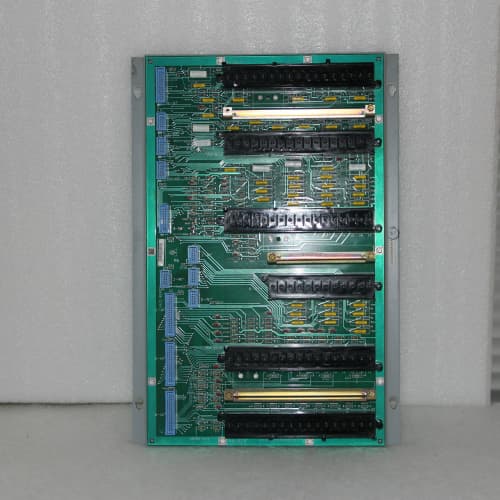
RTD measurements that drift after a few years of thermal cycling aren’t a sensor problem—it’s the termination board’s current source aging out of spec. The DS3800NRMA1C1C is the ruggedized version of GE’s dedicated RTD board, built with two key upgrades: reinforced terminal blocks (through-hole anchoring so they don’t lift) and a high-Tg PCB material (170°C glass transition temperature) that prevents delamination in warm cabinets.
What you get is a board that survives in the field—not just in climate-controlled control rooms. The 1C revision on the terminal blocks adds through-hole pins to the surface-mount terminal blocks, giving you about 3x the pull-out strength when torquing down 14 AWG RTD extension wire. The 1C PCB material (identical suffix, different attribute) extends the operating temperature range to -25°C to +65°C. A Gulf Coast refinery with outdoor RTD terminations in a non-conditioned enclosure replaced standard NRMAs (which had started showing intermittent faults after 4 years) with these 1C1C boards. After 8 years, not a single failure. The ruggedized construction paid for itself many times over.
Key Technical Specifications
| Parameter | Value |
|---|---|
| Product Type | RTD termination board, ruggedized |
| Board Form Factor | Full-height 6U PCB |
| Input Channels | 16 channels (RTD) |
| Supported RTDs | PT100, PT1000, Ni120 (configurable) |
| RTD Wiring | 2-wire, 3-wire, or 4-wire per channel |
| Excitation Current | 0.5mA ±0.01% (per channel) |
| Excitation Voltage | 1.5V maximum at 0.5mA |
| Lead-Wire Compensation | Automatic per channel (3- and 4-wire) |
| Lead Resistance Range | 0-50Ω (cancellation capability) |
| Measurement Range | -200°C to +850°C (PT100) |
| Resolution | 0.01°C (module-dependent) |
| Accuracy | ±0.1°C (RTD + NRMA combined, -25°C to +65°C) |
| Noise Rejection | 100dB at 60Hz |
| Isolation | 250V AC channel-to-channel, 500V AC to ground |
| Terminal Block Type | Screw-clamp, reinforced through-hole anchoring (1C) |
| Wire Gauge Range | 14-22 AWG solid or stranded |
| Terminal Retention | Solder + through-hole pins |
| PCB Material | FR-4, high-Tg 170°C (1C), 6-layer |
| PCB Thickness | 2.0mm (enhanced rigidity) |
| LED Indicators | Green (active), Yellow (open/over-range), Red (fault) |
| Connector Type | 50-pin header to RTD input module |
| Operating Temp | -25°C to +65°C (extended range) |
| Weight | 0.8 kg (approx. 1.8 lbs) |
| Mounting | Screws to rack chassis (hardware not included) |
Compatible Replacement Models
| Model | Compatibility | Notes |
|---|---|---|
| DS3800NRMA1C1C | ✅ Drop-in Replacement | Exact match. Ruggedized version with reinforced terminals and high-temp PCB. Direct swap. |
| DS3800NRMA (standard) | ✅ Drop-in Replacement | Standard version without the reinforced terminals and high-temp material. Fits the same rack. The 1C1C is a direct upgrade. |
| DS3800NRMA1C | ⚠️ Hardware Difference | Has reinforced terminal blocks but standard-temp PCB. Fits the same rack, but the board may not hold up if your cabinet exceeds 55°C. Labor: 1 hour. |
| DS3800NRMA-1 | ⚠️ Software Compatible | Older revision with a different excitation current (1mA). Requires recalibration in the I/O module configuration. Labor: ~2 hours. |
| DS3800NRCA | ❌ Hardware Difference | General-purpose analog board without precision excitation. Not a direct replacement for RTD use. |
| IS200ERMA (Mark V) | ❌ Hardware Incompatible | Mark V board with different connector pinout and mounting. Not compatible. |
Frequently Asked Questions (FAQ)
What’s the actual difference between the 1C1C and the standard NRMA?
Two specific upgrades:
- The first “1C” denotes reinforced terminal blocks with through-hole anchoring. The terminal blocks have additional pins that go through the PCB and are soldered on the bottom, preventing them from lifting during wire termination or vibration.
- The second “1C” denotes high-Tg (170°C) PCB material that won’t delaminate when your cabinet temperature exceeds 55°C. The standard board uses standard FR-4 (135°C Tg).
The rest—excitation current, accuracy, channel count—is identical. The ruggedized features make the board more durable, not more accurate. It’s the same measurement performance, just in a tougher package.
Can I use the 1C1C in a 125V DC system?
Yes. The board only handles the RTD signal (millivolts) and uses 24V DC power from the backplane. The 125V DC is isolated on the power supply side. The board’s isolation rating (250V AC) covers you—the board will safely handle 125V DC field wiring adjacent to RTD signal wiring, as long as you maintain separation.
What’s the maximum temperature the 1C1C can operate at?
The board is rated for continuous operation at 65°C ambient. In practice, it can handle up to 70°C for short periods (a few hours). The high-Tg PCB material doesn’t soften until 170°C, so the board itself won’t fail—but the terminal blocks and connectors have temperature limits. The plastic housings on the terminal blocks are rated for 105°C, so you have margin. If your cabinet exceeds 65°C, improve your cooling—the I/O modules in the rack will fail before the termination board does.
What’s the benefit of the reinforced terminal blocks?
The standard NRMA uses surface-mount terminal blocks. If you torque a 14 AWG wire to 0.5 Nm (the spec), the terminal block can lift off the PCB over time, especially in vibration. The 1C’s through-hole pins prevent lifting—the mechanical load is transferred to the PCB’s plated-through holes. In pull-out testing, the 1C terminals held 3x the force of the standard terminals before failure. If you’re terminating RTD wires in a high-vibration area, the 1C1C is worth the premium.
Does the 1C1C require different jumpers than the standard NRMA?
No, the jumper configuration is identical. The board uses the same jumpers for RTD type (PT100, PT1000, Ni120) and wiring configuration (2-, 3-, or 4-wire). The ruggedized features don’t change the electrical design—just the mechanical construction. Your existing wiring diagram and jumper settings apply.
Can I hot-swap the 1C1C?
No. The board is connected to live RTD sensors and the I/O module. Pulling it while powered could damage the I/O module’s input stage. Power down the rack, swap the board, and power back up. It’s a 15-minute job. Don’t hot-swap.
What’s the difference between the 1C suffix on the terminals and the 1E suffix on the NPTA?
The 1C and 1E are both through-hole anchoring upgrades. The suffixes vary by board family—GE uses different letters for different product lines. They serve the same purpose: preventing terminal block lifting. The 1C is the NRMA’s ruggedized terminal revision; the 1E is the NPTA’s. Both provide the same mechanical benefit.
How do I test the 1C1C before installation?
Our inbound test:
- Visual: inspect the through-hole solder joints on the terminal blocks—must be full, with no voids or cracks.
- Excitation current test: verify each channel’s current source is 0.5mA ±0.01%.
- Lead-wire compensation test: simulate a 3-wire RTD with known lead resistance (10Ω) and verify the board cancels the lead error.
- Thermal cycling: cycle the board from -25°C to +65°C for 3 cycles while monitoring resistance—must show no intermittent opens.
- Isolation: 500V DC between adjacent channels—must exceed 10MΩ.
We reject about 4% of inbound 1C1C boards—most commonly for poor through-hole soldering on the terminal blocks. The through-hole process requires more care than surface-mount; if the solder doesn’t wick properly, the terminal block isn’t anchored.
What’s the typical application for the 1C1C?
Bearing temperature monitoring in turbine skids, where vibration is high and temperature extremes are common. The 1C1C is overkill for a climate-controlled control room—the standard NRMA is fine there. But if your RTD wiring terminates in a non-conditioned enclosure or on a turbine deck, the 1C1C is the right choice. The extra cost (about 25% over the standard NRMA) is negligible compared to the cost of replacing a failed board or chasing intermittent faults.
What’s the most common failure mode on the 1C1C?
The excitation current source—the board’s most sensitive component. Over time, the current source can drift out of spec (more than 0.01% tolerance). You’ll see the measurement drift slowly—maybe 0.1°C per year. It’s not catastrophic, but it’s enough to cause nuisance alarms on critical RTD loops. We recommend a calibration check every 5 years. The terminal blocks, thanks to the through-hole anchoring, rarely fail—they’re the board’s most reliable component. The 50-pin header connector is the second-most common failure—it can have bent pins from mishandling.
A-B MPL-B540K-SJ24AA
SIEMENS 1FK7105-5AC71-1EH0
ŷ 1FK7105-5AC71-1EH0
ABB 3HNE00313-1
 Email: sales@plcfcs.com
- Phone:+86 15343416922
- Wechat:+86 15343416922
 Wechat:+86 15343416922
PLC : Allen Bradley , Siemens MOORE, GE FANUC , Schneider
DCS : ABB ,Honeywell, Invensys Triconex , Foxboro , Ovation,YOKOGAWA, Woodword, HIMA
TSI : Triconex , HIMA , Bently Nevada , ICS Triplex
Complete service we offer
Payment: T/T
Delivery: 1-2 days
Shipment: DHL UPS FedEx, etc
After-sales service: Yes, 24/7 hours