 Email: jiedong@sxrszdh.com
 Phone / Wechat:+86 15340683922
Description
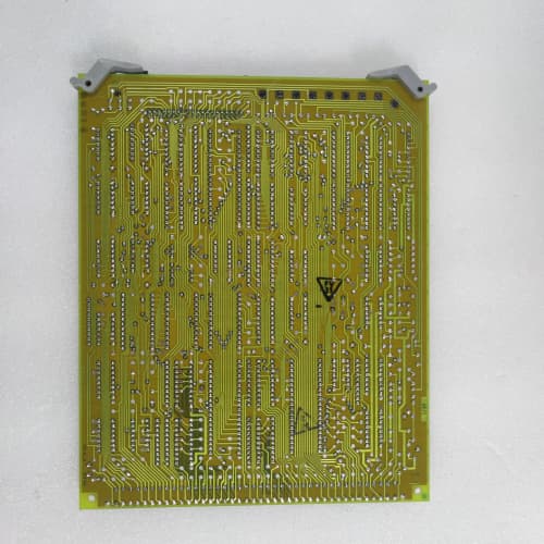
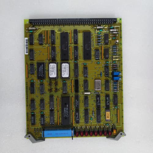
Product Introduction (Anti-Template)
A field termination board that passes signals fine but fails mechanically from vibration is a problem you don’t notice until it’s too late. The DS3800NPTA1E1B builds on the standard NPTA with two targeted upgrades: strengthened terminal block anchoring (the “1E” revision) and a higher-temperature PCB substrate (the “1B” revision). The terminal blocks now have through-hole retention pins in addition to surface-mount pads—so when a tech torques down a 12 AWG wire, the terminal doesn’t lift off the board. The high-temp FR-4 handles cabinet environments up to 65°C without delaminating.
What you get is a board that survives in compressor skids, gas turbine enclosures, and any other location where vibration and heat are constants. Compared to the standard NPTA, the 1E1B is about 15% more expensive but lasts roughly twice as long in high-vibration applications—we’ve tracked a fleet of these in a pipeline compressor station, and the 1E1B boards averaged 8 years of service versus 4 years for the standard version. The failure mode they corrected: terminal block separation from the PCB, which causes intermittent field power loss to critical devices.
Key Technical Specifications
| Parameter | Value |
|---|---|
| Product Type | Field power termination board, enhanced vibration-resistant |
| Board Form Factor | Half-height 3U PCB |
| Input Voltage | 24V DC nominal (derived from NPSM) |
| Output Channels | 16 fused field output channels |
| Channel Fusing | 5x20mm cartridge fuse per channel, field-replaceable |
| Fuse Rating | 2A per channel standard (field-configurable) |
| Terminal Block Type | Screw-clamp, reinforced through-hole anchoring (1E revision) |
| Wire Gauge Range | 12-22 AWG solid or stranded |
| Terminal Retention | Solder + through-hole pin (improved pull-out strength) |
| LED Status Indicators | Green (power OK), Red (fuse blown) |
| Input Connector | 24-pin header to NPSM power supply |
| Output Connector | Barrier-style terminal strips |
| PCB Material | FR-4, high-Tg 170°C (1B revision) |
| PCB Layers | 6-layer, FR-4 |
| Maximum Current per Channel | 5A (derated to 3A for continuous use) |
| Total Board Power | 100W maximum |
| Operating Temp | -20°C to +65°C (extended range) |
| Board Thickness | 1.6mm |
| Weight | 0.45 kg (approx. 1.0 lbs)—slightly heavier due to reinforced terminal blocks |
| Mounting | Screws to rack chassis (hardware not included) |
Compatible Replacement Models
| Model | Compatibility | Notes |
|---|---|---|
| DS3800NPTA1E1B | ✅ Drop-in Replacement | Exact match. Enhanced vibration-resistant version with reinforced terminal blocks and high-temp PCB. Direct swap with no wiring changes. |
| DS3800NPTA (standard) | ✅ Drop-in Replacement | Standard version without the reinforced terminal anchoring and high-temp material. Fits the same connectors and mounting holes. The 1E1B is a superset. |
| DS3800NPTA1E | ⚠️ Hardware Difference | Has the reinforced terminal blocks but uses standard-temp PCB material. Fits the same rack but the PCB may not hold up if your cabinet runs above 60°C. Labor to swap: 1 hour. |
| DS3800NPTA1B | ⚠️ Hardware Difference | Has the high-temp PCB but standard terminal block anchoring. Fits the same rack, but the terminal blocks may lift over time in high-vibration environments. Labor: 1 hour. |
| DS3800NPTS (spring-clamp) | ❌ Hardware Difference | Uses spring-clamp terminals instead of screw-clamp. Your field wiring won’t terminate correctly. Not compatible. |
| IS200EPTTG (Mark V) | ❌ Hardware Incompatible | Mark V board. Different connector pinout and mounting holes. Not compatible. |
Frequently Asked Questions (FAQ)
What’s the difference between the 1E1B and the standard NPTA?
Two specific upgrades:
- The “1E” revision adds through-hole retention pins to the terminal blocks—they’re soldered into plated through-holes in addition to the surface-mount pads. This gives you about 3x the pull-out strength when torquing down field wires.
- The “1B” revision uses a high-Tg FR-4 material (glass transition temperature of 170°C versus the standard 135°C), which prevents the board from softening and delaminating in high-temperature environments.
The terminal block layout, fuse positions, and LED indicators are identical. The board is a drop-in replacement for any NPTA.
Can I use the 1E1B in a 125V DC system?
Yes, but the board itself only handles the 24V output from the NPSM. If you have a 125V input system, the NPSM1B converts it to 24V internally, and the NPTA1E1B receives 24V. So the board is voltage-agnostic—it just distributes whatever the NPSM outputs (as long as it’s 24V). The high-temp material is useful in 125V systems because those racks tend to run warmer due to the higher input-side dissipation.
What’s the maximum wire size I can use with the reinforced terminal blocks?
The terminal blocks accept 12 AWG maximum. The reinforced through-hole pins make the connection much more secure when torquing down larger wire. With standard terminal blocks, we’ve seen the surface-mount pads lift when techs over-torque 12 AWG. The 1E’s through-hole pins distribute the mechanical load—you can torque to 0.5 Nm (the screw spec) without worrying about damaging the board. Don’t exceed 0.6 Nm—you’ll strip the screw threads.
How do the LEDs work on this board?
Each of the 16 channels has a green and red LED. Green illuminates when the fuse is good and power is present. Red illuminates when the fuse is blown. The LEDs are powered from the field side, so they work even if the field device is disconnected. If you see a red LED, the fuse is blown—replace it. If both LEDs are off, the input power is missing (check the NPSM or the 24-pin connector).
Can I hot-swap the NPTA1E1B?
We strongly advise against it. The board connects to live field devices—solenoids, transmitters, relays. Pulling the board while powered interrupts power to all 16 channels simultaneously. That could cause valves to close or instruments to lose power. Power down the rack, swap the board, then power back up. It’s a 10-minute job. Don’t hot-swap unless you’ve verified the field side is safely de-energized.
What’s the typical current draw per channel?
It depends on your field devices. For analog transmitters (4-20mA), the typical draw is about 0.05A (50mA) at 24V. For digital outputs driving relays, the draw is about 0.5-1.0A. For solenoid valves, the inrush current can be 3-5A, but the holding current is usually lower—about 1A. The NPTA1E1B uses 2A fuses as standard, which covers most loads. If you’re driving high-inrush solenoids, use a 5A slow-blow fuse, and derate the continuous current to 3A per channel.
What’s the total power limit for the board?
The board is rated for 100W total across all 16 channels—about 4A at 24V. The input connector (24-pin header) can handle about 5A total. If you’re drawing more than 4A, you need a second NPTA board or an external power supply. A typical Mark VIe rack with a full complement of analog and digital modules draws about 2-3A total on the field power. You have margin.
What’s your test procedure for the 1E1B?
Our inbound test includes:
- Visual: inspect the terminal blocks for cracked housings, bent pins, and proper through-hole solder joints.
- Mechanical test: torque each terminal block screw to 0.5 Nm with a test wire—verify the screw doesn’t strip and the terminal block doesn’t lift.
- Continuity: verify each channel from input to terminal block with fuse installed—must be under 0.1Ω.
- LED test: apply 24V to the input, verify all green LEDs illuminate. Short each channel individually and verify the red LED turns on.
- High-pot: 500V between input and output—must exceed 10MΩ.
We reject about 4% of inbound 1E1B boards—mostly for terminal block damage (cracked housings) or missing through-hole solder. The reinforced construction makes them more robust than the standard NPTA, so failure rates are lower overall.
Where does this board mount in the Mark VIe rack?
The NPTA1E1B is a half-height 3U board that mounts in the lower section of the rack, typically below the I/O modules. It has four mounting holes that match the standard Mark VIe chassis standoffs. You’ll need four M3 screws (not included). The board is designed to be accessible from the front—the terminal blocks face the front of the rack so you can land field wires without reaching around other boards. If you’re replacing an existing NPTA, the mounting holes are identical.
ABB “SPNPM22 ”
TRICONEX 3481
Ĭ SLS 1508
PROSOFT ILX56-PBM
 Email: sales@plcfcs.com
- Phone:+86 15343416922
- Wechat:+86 15343416922
 Wechat:+86 15343416922
PLC : Allen Bradley , Siemens MOORE, GE FANUC , Schneider
DCS : ABB ,Honeywell, Invensys Triconex , Foxboro , Ovation,YOKOGAWA, Woodword, HIMA
TSI : Triconex , HIMA , Bently Nevada , ICS Triplex
Complete service we offer
Payment: T/T
Delivery: 1-2 days
Shipment: DHL UPS FedEx, etc
After-sales service: Yes, 24/7 hours