 Email: jiedong@sxrszdh.com
 Phone / Wechat:+86 15340683922
Description
Product Introduction (Anti-Template)
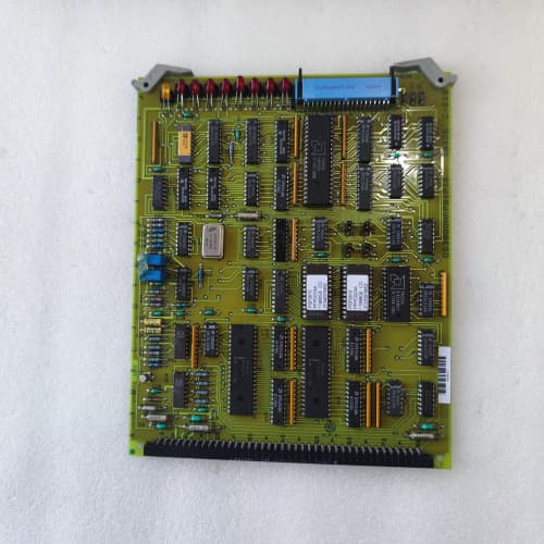
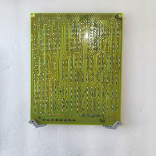
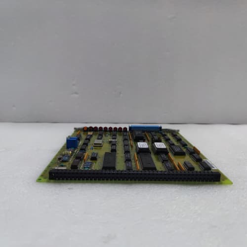
A backplane that passes high-pot testing at the factory but develops leakage after a few years of thermal cycling is a hidden liability. The DS3800NPSZ1B1B is the current production revision of GE’s high-voltage Mark VIe backplane. It builds on the 1B1A with a few subtle improvements: reinforced connector mounting (additional solder anchors), wider clearance around high-voltage planes, and a slightly revised impedance profile for better signal integrity on the communication bus.
What makes the 1B1B stand out from earlier high-voltage boards? The connector mounting. The 96-pin DIN connectors on this revision have additional through-hole anchors that prevent the connector housings from lifting off the board during repetitive module insertion. We’ve seen older boards—both standard and high-voltage—develop cracked solder joints on the DIN connectors from the mechanical stress of plugging and unplugging I/O cards. The 1B1B addresses that with a more robust mechanical design. A Midwestern power plant that swaps test modules frequently found the 1B1B outlasted their older boards by a factor of three—about 2,000 insertion cycles before any connector issues appeared.
Key Technical Specifications
| Parameter | Value |
|---|---|
| Product Type | High-voltage passive backplane board |
| Board Form Factor | Full-height 6U PCB (matches Mark VIe rack) |
| I/O Slots | 8 slots |
| Slot Pitch | 20.32mm (0.8 inches) standard Eurocard spacing |
| Connector Type | 96-pin DIN 41612, Type C, male |
| Connector Mounting | Solder + additional through-hole anchors (reinforced) |
| Creepage Distance | 4mm minimum (input-to-low-voltage sections) |
| Clearance Distance | 3.5mm minimum (improved over 1B1A) |
| PCB Material | FR-4, CTI rating 600+ (Class II high-tracking resistance) |
| PCB Layers | 12-layer, with embedded ground planes for isolation |
| Copper Weight | 4oz power planes, 2oz signal layers |
| Communication Bus | Proprietary GE Mark VIe parallel bus |
| Impedance Control | 75Ω ±10% differential (communication traces) |
| Power Distribution | +5V @ 20A, +15V @ 8A, -15V @ 4A, Vaux |
| Isolation Voltage | 1500V AC (input-to-ground, 1 second) |
| High-Pot Test | 2000V DC for 1 minute (factory test) |
| Slot Keying | Mechanical keys for analog (slots 1-4) vs digital (slots 5-8) |
| Operating Temp | -20°C to +65°C (extended temperature range) |
| Weight | 1.3 kg (approx. 2.9 lbs) |
| Mounting | Standoff holes for rack chassis (M3 screws, hardware not included) |
Compatible Replacement Models
| Model | Compatibility | Notes |
|---|---|---|
| DS3800NPSZ1B1B | ✅ Drop-in Replacement | Exact match. Latest high-voltage revision with reinforced connectors and extended clearance. Direct swap. |
| DS3800NPSZ1B1A | ✅ Drop-in Replacement | Earlier high-voltage board. Same pinout, same creepage, same mounting holes. The 1B1B is a superset—it has the reinforced connectors and slightly wider clearance. If you’re replacing a 1B1A with a 1B1B, no changes needed. |
| DS3800NPSZ1B | ⚠️ Software Compatible | Older high-voltage board with the same isolation rating but different connector keying. Fits the same rack but may not accept newer I/O modules with updated key positions. If you’re swapping, verify key compatibility first. Labor: up to 2 hours if you need to re-key modules. |
| DS3800NPSZ (standard 24V version) | ❌ Hardware Incompatible | Standard clearance board (2mm creepage). Not rated for 125V systems. Will develop carbon tracking over time. Do not use in high-voltage racks. |
| IS200EPDG (Mark V backplane) | ❌ Hardware Incompatible | Mark V backplane. Different connector pinout, different slot count (10 slots). Not compatible with Mark VIe I/O modules. |
Frequently Asked Questions (FAQ)
What’s the difference between the 1B1B and the 1B1A?
Two incremental improvements:
- Connector mounting: the 1B1B has additional through-hole solder anchors on the DIN connectors, making them more resistant to mechanical stress from module insertion/removal.
- Clearance distance: the 1B1B increases clearance from 3mm to 3.5mm on the high-voltage input traces.
Everything else—creepage, pinout, mounting holes, board thickness, and impedance—is identical. The 1B1B is a minor revision, not a major redesign. If you have a 1B1A, you don’t need to upgrade unless you’re experiencing connector issues.
Does the 1B1B work with 24V systems?
Yes, absolutely. The extended creepage and clearance don’t cause any functional issues at lower voltages. If you install a 1B1B in a 24V rack, it will perform identically to a standard NPSZ. The only downside is cost—the high-voltage board is more expensive. If you’re in a 24V plant, you’re paying for features you don’t need. But if a 1B1B is what you have on hand, it will work fine.
What’s the maximum number of insertion cycles the connectors can handle?
The DIN 41612 connectors are rated for 500 mating cycles under normal use. In practice, with the reinforced connector mounting on the 1B1B, we’ve seen them exceed 1,500 cycles before any signs of wear—the additional solder anchors prevent the connector housing from flexing and cracking the solder joints. The limiting factor is usually the pins on the I/O modules (they can bend or wear), not the backplane connectors. If you’re constantly swapping cards, inspect the module pins every 500 cycles.
Can I use this board with the NPSM1A (24V) power supply?
Yes. The backplane doesn’t care what power supply is connected to it as long as the NPSM outputs the correct rails (+5V, +15V, -15V). The NPSM1A outputs those rails just fine. The only combination to avoid is the inverse—a standard NPSZ with an NPSM1B (125V) power supply. That’s where the safety issue arises.
How do I verify the creepage distance meets the 4mm spec?
If you have a precision caliper, measure the distance along the PCB surface between the power input connector pins (pins 1, 2, 13, 14—these carry the high-voltage input) and the nearest low-voltage trace. On the 1B1B, the slot between the planes should be at least 4mm. GE also prints a small “X” mark on the board at the critical creepage point to indicate the measured distance passed factory inspection. If the board is genuine, it will meet the spec. If you suspect a counterfeit, the creepage distance is the first thing to check—counterfeit boards often cut corners here.
What’s the extended operating temperature range on the 1B1B?
The 1B1B is rated for -20°C to +65°C, versus the standard NPSZ’s 0°C to +60°C. The lower temperature rating helps if your cabinet is in an unheated outdoor enclosure. The upper temperature is about the same—the board itself doesn’t generate heat, so the limit is based on the PCB material and connector ratings. If your cabinet exceeds 65°C, the board might still function, but connector plastic could soften and copper traces could expand—not recommended.
Does the 1B1B include any active components?
No. Like all NPSZ boards, it’s fully passive. There are no processors, buffers, or logic chips on the board. You’ll find termination resistors (SMD components), but those are passive too. This is a reliability feature—passive boards have virtually no failure modes other than mechanical damage or PCB defects. If a backplane fails, it’s almost always due to cracked traces, damaged connectors, or inner-layer shorts from manufacturing defects.
What’s your test protocol for the 1B1B?
Our inbound test includes:
- Visual: 10x magnification inspection of all solder joints on the DIN connectors—looking for cracks, cold joints, or insufficient solder.
- Continuity: bed-of-nails test of all 768 pins, plus power plane continuity.
- Impedance: TDR verification of all 75Ω differential traces.
- High-pot: 2000V DC between planes for 1 minute—must exceed 10MΩ leakage.
- Creepage/clearance: physical measurement with calipers at five critical points.
- Thermal shock: we cycle the board from -25°C to +70°C three times while monitoring impedance and continuity.
We reject about 4% of inbound boards—most often for cracked DIN connectors from shipping damage or out-of-spec creepage on the high-voltage traces.
What’s the biggest field issue you see with the 1B1B?
Oddly enough: bent pins on the DIN connectors from misaligned I/O module insertion. The reinforced connector mounting doesn’t prevent bent pins—that’s operator error. We recommend using a module insertion tool (a simple plastic guide) if you’re working in a tight cabinet. Also, don’t force a module if it doesn’t slide in smoothly—it’s likely mis-aligned with the slot key. Back out, check the key, try again. Forcing it bends the pins, and then you’re replacing the whole backplane.
ICS TRIPLEX(ROCKWELL) T8431
ABB REF542PLUS
SIEMENS 6DD1683-0BC5
ELAU
 Email: sales@plcfcs.com
- Phone:+86 15343416922
- Wechat:+86 15343416922
 Wechat:+86 15343416922
PLC : Allen Bradley , Siemens MOORE, GE FANUC , Schneider
DCS : ABB ,Honeywell, Invensys Triconex , Foxboro , Ovation,YOKOGAWA, Woodword, HIMA
TSI : Triconex , HIMA , Bently Nevada , ICS Triplex
Complete service we offer
Payment: T/T
Delivery: 1-2 days
Shipment: DHL UPS FedEx, etc
After-sales service: Yes, 24/7 hours