 Email: jiedong@sxrszdh.com
 Phone / Wechat:+86 15340683922
Description
Product Introduction (Anti-Template)
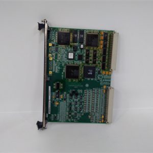
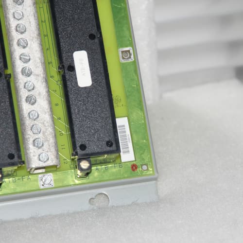
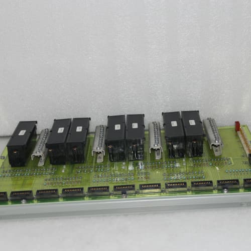
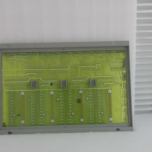
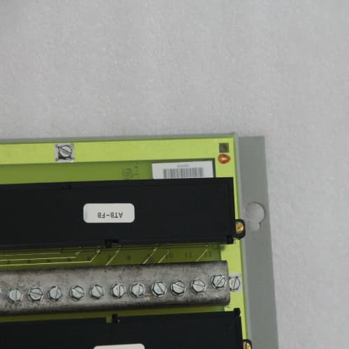
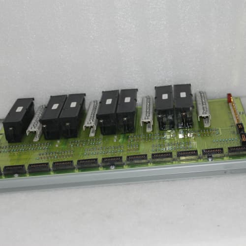
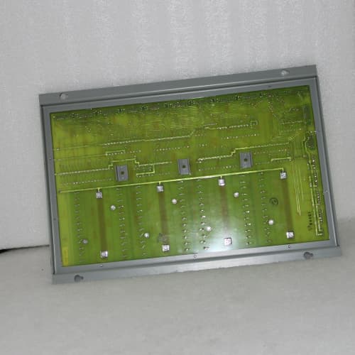
A cracked backplane trace is the kind of failure that makes you question every other component in the rack—because the symptoms look like a bad power supply, a faulty I/O card, or a loose cable. The DS3800NPSZ is the passive backplane that ties everything together in a Mark VIe rack. It’s a multi-layer PCB with eight 96-pin DIN connectors, power distribution planes, and a communication bus that links the I/O modules to the CPU.
What makes the NPSZ different from a generic backplane? The controlled impedance on the communication traces (75Ω differential) and the heavy copper planes (4oz) for the +5V and +15V rails. That 4oz copper matters when you’re distributing 20A across the board—voltage drop between slots is under 10mV, which keeps all your I/O cards seeing the same clean supply. A plant in Texas replaced a backplane with a cracked inner layer (invisible to the naked eye) that had been causing random slot errors for three months. The plant had replaced two I/O cards and a power supply before they finally swapped the backplane. Problem solved.
Key Technical Specifications
| Parameter | Value |
|---|---|
| Product Type | Passive backplane board |
| Board Form Factor | Full-height 6U PCB (matches Mark VIe rack) |
| I/O Slots | 8 slots |
| Slot Pitch | 20.32mm (0.8 inches) standard Eurocard spacing |
| Connector Type | 96-pin DIN 41612, Type C, male |
| Communication Bus | Proprietary GE Mark VIe parallel bus (75Ω differential) |
| Power Distribution | +5V @ 20A, +15V @ 8A, -15V @ 4A, Vaux |
| Copper Weight | 4oz power planes, 2oz signal layers |
| PCB Layers | 10-layer, FR-4 material |
| Impedance Control | 75Ω ±10% differential (communication traces) |
| Slot Keying | Mechanical keys for analog (slots 1-4) vs digital (slots 5-8) |
| Termination | On-board termination resistors for bus signals |
| Mounting | Standoff holes for rack chassis (M3 screws) |
| Operating Temp | 0°C to +60°C |
| Weight | 1.2 kg (approx. 2.6 lbs) |
Compatible Replacement Models
| Model | Compatibility | Notes |
|---|---|---|
| DS3800NPSZ | ✅ Drop-in Replacement | Exact match. Same slot count, same connector spacing, same impedance control. Direct swap with no configuration changes. |
| DS3800NPSZ-1 | ⚠️ Software Compatible | Older revision with slightly different bus termination resistors (changed from 75Ω to 82Ω to improve noise margin). Fits the same rack, but you may need to verify your CPU firmware version. If you’re on ToolboxST v5.0 or earlier, the bus timing may be marginal. Labor to swap: ~2 hours including validation. |
| DS3800NPSZ-2 | ⚠️ Hardware Difference | Revision that added optional slot keying for high-power modules. Same pinout, but the mechanical slot keys are positioned differently. You may need to swap the plastic keys on your I/O modules. Not a direct drop-in if your modules have the older keying. |
| IS200EPDG (Mark V backplane) | ❌ Hardware Incompatible | Mark V backplane with 10 slots and different connector pinout. Not compatible with Mark VIe I/O modules. |
| Third-party backplane | ❌ Hardware Incompatible | Generic VME or Eurocard backplanes will not match the proprietary Mark VIe bus timing and pinout. Don’t attempt it. |
Frequently Asked Questions (FAQ)
What’s the difference between a “passive” backplane and an “active” one?
A passive backplane has no active electronic components—no processors, no buffers, no logic gates. It’s just a PCB with traces connecting the slots to each other and to the power and communication busses. An active backplane might have bus arbitration chips, signal conditioning, or even a small CPU. The NPSZ is passive, which means it’s reliable and field-replaceable. There’s nothing to fail except the PCB itself (traces, vias, and connectors). If it fails, you swap it. No firmware, no configuration.
How do I know if my backplane is faulty?
Common failure signs:
- Intermittent failures that change slot to slot (a bad backplane will affect multiple slots).
- Communication errors on specific I/O cards, but those cards work fine in another rack (this is the classic test—swap the card to a known-good rack).
- Voltage at the backplane connectors is low or inconsistent across slots.
- Visible damage—burnt traces, cracked PCB near the mounting screws, or bent pins in the DIN connectors.
The tricky failure is an inner-layer crack—you can’t see it, and it only fails when the board warms up. If you suspect the backplane, swap it with a known-good unit. It’s the most definitive test.
Can I replace the DIN connectors on the NPSZ if they’re damaged?
The 96-pin DIN connectors are soldered through-hole components. It’s technically possible to replace them if you have a desoldering station and the right tools, but we don’t recommend it. The risk of damaging the plated-through holes is high—and then you’ve got an even bigger problem. We’ve seen a plant try this with a cheap soldering iron and they lifted three pads. Just replace the whole board. It’s less expensive than the labor to troubleshoot a partially repaired board.
What’s the purpose of the slot keying on the NPSZ?
Slot keying prevents you from plugging an I/O card into the wrong slot. Slots 1-4 are keyed for analog input/output modules (they have a different notch position than digital modules). Slots 5-8 are keyed for digital modules. If you try to insert a digital module into slot 1, the plastic key will physically prevent it from seating. This protects the module and the backplane from mis-wiring. We’ve seen a plant file down the keys to “make it fit”—they fried a digital output card. Don’t do that.
What’s the maximum current I can draw from the backplane?
The NPSZ distributes up to 250W total from the power supply. That’s a system-wide limit, not a per-slot limit. The backplane itself can handle 30A on the +5V rail and 15A on the +15V rail (it’s designed for the full capacity of the NPSM supply). However, the NPSM is rated for 20A on +5V and 8A on +15V. So the backplane isn’t the bottleneck—the power supply is. The backplane will happily carry whatever the NPSM delivers. In practice, most racks pull 15A on +5V and 5A on +15V.
My rack has a “slot 0” next to the power supply. Is that an I/O slot?
No. Slot 0 is typically a filler or a dedicated CPU slot on some Mark VIe configurations. However, the NPSZ only provides eight connectors for I/O modules—slots 1-8 are the actual I/O slots. The CPU may be mounted on a separate carrier board or in a different rack depending on your system architecture. Consult your system drawing. If you’re using a standard I/O rack, you won’t use slot 0.
Can I use the NPSZ with 125V DC input systems?
Yes. The backplane doesn’t care about the input voltage—it only distributes the output rails from the NPSM. The NPSM converts the input (24V or 125V) to the +5V, +15V, and -15V rails. The backplane just passes those rails to the I/O slots. So a single NPSZ works with both the 24V and 125V versions of the system. The voltage rating on the board is 300V for all traces, so 125V is well within spec.
What’s the typical failure rate for the NPSZ?
Backplanes are among the most reliable components in a Mark VIe rack. They have no moving parts, no active components, and no thermal cycling issues if the rack is properly cooled. We see failure rates under 1% over 10 years in controlled environments. The most common failure mode is damaged DIN connectors from rough module insertion or bent pins from mis-alignment. Mechanical damage accounts for about 80% of the failures we see. Electrical failures (cracked traces, shorted planes) are rare. The NPSZ is a board you replace once and forget about.
How do you test a surplus NPSZ before shipping?
Our inbound test protocol:
- Visual: inspect all DIN connectors for bent pins, cracked housings, or damaged plastic keys. Check for PCB delamination, burn marks, or cracked corners.
- Continuity: verify every pin on every connector has continuity to its destination (power planes, bus traces, or termination resistors). We use a bed-of-nails fixture for this—it’s automated and tests all 768 pins (8 slots x 96 pins).
- Impedance: verify the bus traces are within the 75Ω ±10% spec using a TDR (time-domain reflectometer).
- Power plane test: apply 5V to the power plane and verify voltage at every slot (must be within ±2%).
- High-pot: 500V DC between planes and between adjacent traces—must exceed 10MΩ.
We reject about 5% of inbound NPSZ boards—most commonly for bent pins or cracked connectors from shipping damage. The boards are repairable (we straighten pins or replace connectors) but if the PCB is cracked, we scrap it.
INDRAMAT MTC-P01.2-E2-A2-NN-NN-FW
A-B 1756-L73
A-B 1756-L73
 Email: sales@plcfcs.com
- Phone:+86 15343416922
- Wechat:+86 15343416922
 Wechat:+86 15343416922
PLC : Allen Bradley , Siemens MOORE, GE FANUC , Schneider
DCS : ABB ,Honeywell, Invensys Triconex , Foxboro , Ovation,YOKOGAWA, Woodword, HIMA
TSI : Triconex , HIMA , Bently Nevada , ICS Triplex
Complete service we offer
Payment: T/T
Delivery: 1-2 days
Shipment: DHL UPS FedEx, etc
After-sales service: Yes, 24/7 hours