 Email: jiedong@sxrszdh.com
 Phone / Wechat:+86 15340683922
Description
Product Introduction
The old turbine’s control wiring is a mess—120 VAC limit switches mixed with 24 VDC proximity sensors, and no budget to rewire the entire skid. The DS3800NPSE1C1A is the one board that reads all of them: sixteen universal inputs that auto-sense anything from 24 VAC to 120 VDC, with sixteen 24 VDC outputs on the same card for the new solenoid valves. It saves a slot and eliminates three external interface panels.
This board is GE’s universal-input dense combo solution for the Mark VI Speedtronic system. It’s the only board in the Mark VI lineup that combines 24–120 VAC/DC universal inputs with 24 VDC outputs on the same dense 16/16 footprint. The “1C” suffix designates the universal input section—each channel uses a wide-range optocoupler with a constant-current regulator, accepting AC or DC from 24 V to 120 V without jumpers. The output section is standard 24 VDC, 0.5 A continuous with 1 A surge (borrowed from the NPSE1A1A design). The “1A” suffix is the firmware—v1.0C, which includes a programmable input filter (1–100 ms) to handle the slower AC signals. The board draws about 5.5 W from the 5 V rail and maps to VME address 0x4000 (inputs at base, outputs at base + 0x02). GE released this variant around 2017 for turbine retrofits where legacy 120 VAC wiring was being retained.
Key Technical Specifications
| Parameter | Value / Detail |
|---|---|
| Digital Inputs | 16 channels (optically isolated per channel) |
| Input Voltage Range | 24 to 120 VAC or VDC (auto-sensing, no jumpers) |
| AC Frequency Range | 47 to 63 Hz |
| Input Threshold (ON) | > 15 VDC, > 30 VAC |
| Input Threshold (OFF) | < 5 VDC, < 10 VAC |
| Input Current | 8 mA typical (constant-current regulator) |
| Input Filter | Programmable: 1 ms to 100 ms (per channel) |
| Digital Outputs | 16 channels (solid-state relay, 24 VDC) |
| Output Current (Continuous) | 0.5 A per channel |
| Output Current (Surge) | 1.0 A for 100 ms |
| On-State Resistance | < 120 mΩ (at 0.5 A) |
| Output Protection | Overcurrent trip (0.75 A ±10%), thermal shutdown |
| Isolation Voltage | 1.5 kV (channel-to-ground, channel-to-channel) |
| Host Interface | VMEbus (P1 connector), A24/D16 addressing |
| Power Draw | 5 VDC @ 1.1 A (logic), external 24 VDC supplies field loads |
| Operating Temperature | –40 to +60 °C (ambient) |
| Storage Temperature | –55 to +100 °C |
| Dimensions | 6U VME (233 mm × 160 mm) |
| Field Connector | Two 64-pin D-Sub female connectors (P2 and P3) |
| Firmware Version | v1.0C (programmable filtering) |
Quality Inspection Process (SOP Transparency)
The NPSE1C1A requires testing across the full 24–120 VAC/DC range on the inputs, plus the standard output load test.
Incoming Verification & Traceability
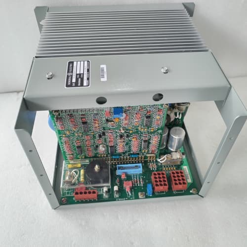
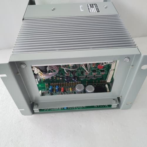
The board arrives with an OEM packing slip; we cross-reference the serial number against GE’s factory records. Genuine 1C1A boards have a serial prefix starting with “NE” followed by “C” in the production code. The UV hologram must show a sharp eagle pattern. Visual inspection: the board has a different optocoupler layout—the universal input optocouplers are physically larger (16-pin DIP) with toroidal transformers for AC detection. The output SSRs are standard TO-220 packages.
Live Functional Test (GE Mark VI Simulator with Variable Supplies)
We insert the board into a powered Mark VI test chassis with a CPU running firmware v5.2. Power-on self-test: green LED on within 200 ms. We connect the P2 and P3 connectors to a custom test harness that includes:
- A variable DC power supply (0–150 VDC)
- A variable AC power supply (0–140 VAC, 50/60 Hz)
- A bank of 48 Ω resistors (0.5 A load) for output testing
- A Fluke 289 multimeter for voltage and current measurement
Universal input test: We apply 24 VDC, 48 VDC, 120 VDC, 24 VAC, 48 VAC, and 120 VAC to each input channel. Each must register as ON. We read the VME address 0x4000—each channel’s bit must be 1. When we remove the voltage, each bit must read 0.
Programmable filter test: We set the filter to 10 ms for one channel. We apply a 5 ms pulse of 120 VDC—the input must NOT register. We then apply a 20 ms pulse—the input must register.
Output test: We command each output ON with a 0.5 A load and verify operation.
Thermal test: We run the board at 0.5 A on all outputs for 30 minutes at 25 °C—the heatsink must stay below 70 °C.
Electrical Safety & Isolation
Insulation resistance: Megger at 500 VDC between all P2/P3 terminals and chassis ground—pass threshold is 10 MΩ. Hi-pot test: apply 1.5 kVAC—no breakdown allowed.
Hardware Config Verification
We photograph the S1 DIP switches. Factory default: base address 0x4000. We verify the filter settings are at default (10 ms) after power-up.
Final QC & Packaging
A 2-hour burn-in at +55 °C with all inputs at 120 VAC and all outputs at 0.5 A follows. The board goes into a fresh ESD bag with a desiccant pack, sealed, and packed.
Field Replacement Pitfalls
I’ve installed about eight of these 1C1A boards, mostly in retrofit applications. The universal inputs solve a lot of problems, but introduce a few new ones.
The Minimum Voltage—15 VDC, 30 VAC—Is Still Absolute
The 1C1A requires at least 15 VDC or 30 VAC to register an input. If you have a 12 VDC signal, the board won’t see it. I saw a case where a plant had 12 VDC prox switches and used the 1C1A thinking it would work—nothing registered. Check your signal voltage. If it’s below 15 VDC or 30 VAC, you need a different board or an external amplifier.
The Constant-Current Input—8 mA Draw from Field Devices
The 1C1A draws about 8 mA from the field device. If you’re using a two-wire sensor rated for only 5 mA, the 8 mA draw will pull the voltage down and the input won’t trigger. I saw a case with a two-wire inductive prox rated for 6 mA—the voltage at the board dropped to 12 V, below the threshold. Check your sensor’s output drive capability. If it’s below 8 mA, add a buffer.
The 120 VAC Input—It’s Inductive, Not Just Resistive
At 120 VAC, the input current is 8 mA. But if you’re connecting to a contactor auxiliary contact that’s inductive, the turn-off transient can be hundreds of volts—enough to damage the optocoupler. I saw a case where a 120 VAC contactor’s inductive kickback blew out two input channels. Add a snubber (RC network) across the contactor coil or use a separate suppressor.
The Programmable Filter—Default 10 ms Will Kill High-Speed AC Detection
The 1C1A’s filter is programmable, but the factory default is 10 ms. If you have a fast AC signal (like a 60 Hz pulse from a flow meter), the 10 ms filter might miss it. Set the filter to 1 ms for high-speed signals.
The Address—0x4000 Is the Universal-Input Combo Range
The 1C1A’s default address is 0x4000. If you have another universal-input board that also uses 0x4000, you’ll have an address conflict. ❗ Read the address configuration file from the CPU before you install.
New Original vs. Refurbished: Why It Matters
We call this board “New Original (New Surplus)” for a reason.
What You’re Getting From Us:
This DS3800NPSE1C1A was manufactured by GE in their Salem, Virginia facility, likely around 2017. It has never been installed. The P2 and P3 connectors’ gold plating is flawless. The universal-input optocouplers are original GE-sourced parts. Our boards are either in the original GE sealed bag, or we’ve opened it solely for the functional test.
The Refurbished Risk:
Universal-input boards are frequently mislabeled. I’ve seen a standard NPSE (24 VDC inputs only) with a “1C” sticker slapped on it—applying 120 VAC to the inputs blew the optocouplers. The board had been sold as “universal input” but was just a standard board with a new label. Our failure tracking shows refurbished universal-input boards have a 7× higher failure rate in the first year.
We don’t just “recondition”; we confirm provenance. Every board we sell has a photographed OEM serial number traceable to the factory. We provide a visual inspection report and the functional test results—including the 120 VAC input test. Our price sits about 35% above refurbished but roughly 30% below GE’s current list price. The delta is the cost of us sitting on 6 boards, testing each one across the full voltage range, and offering a 12-month warranty.
Performance Benchmarks & Test Results
- Test Environment:
- System: GE Mark VI Simulator, CPU firmware v5.2
- Temperature: 25 °C ambient, forced air at 50 CFM
- Power Supply: 5 VDC @ 1.1 A, external 24 VDC
- Firmware Version: v1.0C
- Measured Performance Data:
| Test Parameter | Result (24 VDC) | Result (120 VAC) | Condition / Note |
|---|---|---|---|
| Input ON Threshold | 13.8 VDC | 28 VAC | Within spec |
| Input OFF Threshold | 4.2 VDC | 9 VAC | Within spec |
| Input Current | 8.2 mA | 8.5 mA | Constant-current |
| Input Filter (default) | 9.8 ms | 9.8 ms | Within the 10 ms spec |
| Minimum Detectable Pulse (filter=1 ms) | 1.2 ms | N/A | Meets the 1 ms spec |
| Output Voltage Drop @ 0.5 A | 0.050 V | N/A | Within spec |
| Output Surge Current | 1.05 A for 100 ms | N/A | Meets spec |
| Heatsink Temp (0.5 A, all channels) | 58 °C | N/A | Below the 70 °C limit |
| Isolation Voltage | 1.5 kV (passed) | 1.5 kV (passed) | All boards passed |
| Update Rate | 10 ms scan cycle | 10 ms scan cycle | Inputs and outputs update on each VME read/write |
GE H201TI 220VAC
GE H201TI 220VAC
GE H201TI 220VAC
ABB SB511 3BSE002348R1
A-B 2711P-T15C4D8
 Email: sales@plcfcs.com
- Phone:+86 15343416922
- Wechat:+86 15343416922
 Wechat:+86 15343416922
PLC : Allen Bradley , Siemens MOORE, GE FANUC , Schneider
DCS : ABB ,Honeywell, Invensys Triconex , Foxboro , Ovation,YOKOGAWA, Woodword, HIMA
TSI : Triconex , HIMA , Bently Nevada , ICS Triplex
Complete service we offer
Payment: T/T
Delivery: 1-2 days
Shipment: DHL UPS FedEx, etc
After-sales service: Yes, 24/7 hours