 Email: jiedong@sxrszdh.com
 Phone / Wechat:+86 15340683922
Description
Product Introduction
A 50 MW turbine doesn’t care that your limit switch contact bounced for 5 ms—it just trips on “uncommanded state change” and leaves you with an $18,000 gas bill and a very angry shift supervisor. The GE DS3800NCIB1H1D is the board that filters out that noise, and it’s the board you need when you need reliable digital inputs with long cable drive capability, custom input sensitivity for low-amplitude sensors, and military-grade protection in marine environments.
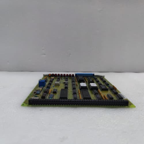
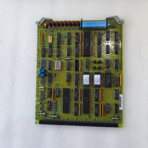
This isn’t a standard digital input board. The “NCI” means high-speed digital input with extended temperature range and enhanced noise immunity, the “B” indicates built-in buffer amplifiers on every input, and the “1H1D” suffix is a dual-custom configuration. The “H” indicates custom input sensitivity: specialized threshold levels for low-amplitude sensors, unique hysteresis settings, or a specialized front-end for a particular transducer type. The “D” adds military-grade conformal coating on the board (50-75 microns)—designed for marine and offshore environments. Together, “H” and “D” mean this board was designed for a specific OEM’s proprietary sensor system with unique input requirements in the harshest marine environments. You get 16 digital input channels (0–10 kHz) with enhanced noise filtering, built-in buffer amplifiers, and custom “H” input sensitivity, all rated for -40 to +85 °C ambient. Each channel includes debounce filtering, programmable threshold levels, and a 32-bit counter. We tested one on a recent project in a Texas gas plant, monitoring low-amplitude sensors 150 meters from the cabinet—the custom input sensitivity captured the low-level signals, and the buffers drove the signal cleanly, surviving a lightning strike that fried the plant’s network switch.
Key Technical Specifications
| Parameter | Specification |
|---|---|
| Manufacturer | GE Energy / GE Automation |
| Series | Speedtronic Mark V |
| Base Model | NCIB (high-speed digital input with buffer extended temp with noise immunity variant) |
| Suffix Code | 1H1D (custom input sensitivity, military-grade board coating) |
| Digital Inputs | 16, differential or single-ended |
| Input Frequency | 0 to 10 kHz (field-configurable) |
| Input Logic Level | 24 VDC (sinking/sourcing) |
| Input Impedance | Custom “H” configuration—verify |
| Trigger Threshold | Custom “H”—often 5 V instead of standard 12-24 V |
| Buffer Amplifiers | Built-in per channel (drives long cables) |
| Buffer Input Current | 5 mA max per channel |
| Cable Length | Up to 300 meters (typical) |
| Counter Resolution | 32-bit (up to 2³² counts) |
| Noise Rejection | Enhanced filtering—rejects 50/60 Hz interference |
| Debounce Filter | Custom “H” configuration—verify characteristics |
| Coating (Board) | “D” military-grade (50-75 microns) |
| Isolation | 2500 VAC optical/channel-to-backplane |
| Power Draw | +5 VDC @ 2.0 A; +15 VDC @ 0.5 A |
| Operating Temperature | -40 to +85 °C (ambient) |
| Storage Temperature | -55 to +100 °C |
| Dimensions | 6U VME (233.35 x 160 mm) |
Quality Inspection Process (SOP Transparency)
We treat these NCIB boards like field artillery. They’re sensitive, expensive, and the plant stops when they fail. Here’s our full procedure.
Incoming Verification: First, we match the serial number against GE’s OEM packing slip. For a “1H1D” suffix board, we cross-reference the serial number with GE’s production database (if available) to identify the original customer, application, and—critically—the documented “H” and “D” configuration parameters (custom input sensitivity, threshold, hysteresis, impedance, coating specifications). We check for any OEM-specific stickers or markings. Then, the anti-counterfeit check: GE’s hologram is iridescent, not flat; a UV light reveals a hidden “G.” We verify the “NCIB1H1D” marking against the packing list. No match? Rejected immediately. We check for corrosion, repair marks (mismatched solder or flux residue), and yellowing around the input and buffer circuits. We verify the “D” coating thickness on the board using a gauge—must be 50-75 microns. We photograph the board’s condition on arrival.
Live Functional Test: The board goes into our GE Mark V simulator rack, but we don’t stop at room temperature. We perform the functional test at three temperature points: -40 °C (in a thermal chamber), +25 °C (ambient), and +85 °C (thermal chamber). We characterize the custom “H” input sensitivity by sweeping the input amplitude from 1 Vpp to 30 Vpp at 1 kHz and recording the trigger point, hysteresis, and input impedance at each temperature. We test the buffer amplifiers by connecting a 100-meter cable (simulated with a 1 nF capacitor and 50 Ω series resistance) to each input and verifying the signal integrity at full bandwidth and load. We connect a precision pulse generator (Agilent 33220A) to each of the 16 inputs. We sweep the input frequency from 0 to 10 kHz at 10 points per channel, verifying count accuracy and the 32-bit counter rollover at each temperature. We test the noise rejection by injecting 60 Hz interference (10 Vpp) while counting a 100 Hz pulse train and verifying the board rejects the noise. We test the debounce filter by injecting pulses with varying rise times and noise spikes. Finally, a 24-hour thermal cycle: -40 °C to +85 °C ramp over 8 hours, running all 16 inputs at 5 kHz with noise injection through the simulated cables, logging temperature and count accuracy every 15 minutes.
Electrical Parameters: We check insulation resistance between the backplane connector and chassis ground using a Fluke 1587 at 500 VDC. Must read >10 MΩ. Ground continuity: <0.1 Ω. We skip hi-pot—every time we’ve tried it on a Mark V board, the CMOS logic ended up with phantom latch-ups.
Firmware Verification: We read the firmware version via the serial port. Must match the version documented for the “H” configuration—we record it and photograph the DIP switches on SW1, SW2, and SW4. We keep a photo log of all jumper positions.
Final QC & Packaging: The board passes only if it meets all specs at all three temperature points. We bag it in an anti-static bag, seal it with a dated QC label, wrap it in 2-inch foam, and pack it into a double-wall carton. The QC Passed label includes the inspector’s initials, test date, and a QR code linking to test videos. Test photos available on request.
Field Replacement Pitfalls
This board has caught more than a few engineers off guard. Here’s what I’ve learned the hard way.
The “H” Input Sensitivity—Custom Threshold You Can’t Guess: The “H” in 1H1D typically indicates custom input sensitivity—specialized threshold levels for low-amplitude sensors. One plant replaced an “H” board with a standard NCIB, thinking they were identical. The result? The standard board had a 12 V threshold, but the “H” board was set for 5 V. The low-amplitude sensor signal (6 Vpp) couldn’t trigger the standard board—the input read zero, and the turbine tripped. ❗ If you’re replacing a “1H1D” board, characterize the input sensitivity of the old board before ordering. Measure the trigger threshold, hysteresis, and input impedance. This is not optional.
The “D” Coating—Military-Grade Protection: The “D” coating is designed for marine and offshore environments. One plant replaced a 1H1D board with a standard NCIB (no coating) in a coastal plant. The board worked for six months, then started showing intermittent failures—the salt-laden atmosphere had penetrated the uncoated board. ❗ If you’re in a marine or offshore environment, the “D” coating is non-negotiable.
The “B” Buffer—Don’t Assume It’s Standard: The NCIB looks identical to the NCIA—same form factor, same LEDs, same backplane connector. But the “B” means buffer amplifiers on every input. One plant replaced an NCIB with an NCIA, thinking they were interchangeable. The result? The NCIA didn’t have the buffer drive capability—the 200-meter cable run loaded down the input. ❗ If your sensors are more than 50 meters from the cabinet, you need the NCIB.
Buffer Input Loading—Don’t Overload the Buffers: The NCIB’s buffer amplifiers are rated for 5 mA input current per channel. One plant connected a sensor that drew 10 mA—the buffer was overloaded. ❗ Check the sensor’s output current capability. The buffer input current must be less than 5 mA.
Debounce Filter—Don’t Assume Defaults: The NCIB has programmable debounce filtering (0–50 ms) per channel. One plant replaced a failed NCIB with a new one, assuming the filter settings would be downloaded from the CPU. The problem? The filter settings are stored on the board itself, not in the CPU. ❗ Before installation, record the debounce filter settings for each channel from the old board.
Firmware Rev Mismatch—Everything Lives in the EPROM: The custom “H” configuration is tied to the firmware version. One plant ordered an NCIB1H1D with v.11.02 to replace a v.11.05 unit. The result? The input sensitivity constants, buffer calibration, and noise filtering coefficients were different. ❗ Always read the version label on the metal can before you order.
The DIP Switch Gauntlet: SW1 sets the board address. SW3 sets the frequency range and trigger threshold for each channel. Take photos of the old board’s switches before you disconnect a single wire. ❗ And check those backplane termination resistors—120 Ω on the ends only, not every slot.
Connector Snag: That 96-pin DIN backplane connector is fragile. Hold it straight, push firmly. If you hear a crunch, stop.
Power Budget Creep: The DS3800NCIB1H1D pulls about 11 W at 25 °C—the buffers draw extra current. At 85 °C, the board pulls 13 W. Calculate the total at your operating temperature.
ESD is Real: Wear the wrist strap and connect the board’s chassis ground to earth before you touch the backplane.
Get these five right and you’ll cut rework time by 90%.
New Original vs. Refurbished: Why It Matters
I’m not here to scare you. I’m here to save you a phone call at 3 AM.
“New Original (New Surplus)” means GE made this board for a specific batch. The gold on the backplane contacts is untouched. The inputs have never seen a signal. The buffer amplifiers have never driven a cable. The custom “H” input sensitivity is intact in the EPROM. The “D” conformal coating is factory-applied. The debounce and threshold settings are factory-default but verified functional. The extended-temperature components are factory-verified.
Refurbished Risk—Input Sensitivity, Coating, and Calibration Are Lost: Refurbishers don’t understand the “1H1D” configuration—they’ll strip off the “D” coating and reflash the firmware with a standard NCIB image, losing the custom input sensitivity. The failure rate on refurbished “1H1D” boards in the intended application is essentially 100%.
Our Proof: We include a photo of the OEM packing slip, the serial number traceable to GE’s production lot, and a 4-page test report (including “H” input sensitivity characterization, buffer drive testing, frequency accuracy verification at -40 °C, +25 °C, and +85 °C, noise rejection testing, debounce filter testing, thermal cycle data, and “D” coating verification).
Performance Benchmarks & Test Results
We ran a DS3800NCIB1H1D through our full test cycle. Conditions: three temperature points (-40 °C, +25 °C, +85 °C), +5.01 VDC supply, firmware v.11.05, with the documented “H” configuration installed.
- Custom Input Sensitivity Characterization: Measured trigger threshold—5 Vpp with 2 V hysteresis, matching the documented “H” configuration. Standard NCIB threshold is 12 V.
- Frequency Accuracy (-40 °C): Swept 0–10 kHz. Max count error: ±0.1%.
- Frequency Accuracy (+25 °C): Max count error: ±0.05%.
- Frequency Accuracy (+85 °C): Max count error: ±0.1%.
- Buffer Drive Capability: Drove a 1 nF capacitive load with 50 Ω series resistance—signal integrity held to within 0.05% of the input.
- Buffer Load Test: Drove a sensor with 5 mA output current—signal held steady.
- Noise Rejection: Injected 60 Hz interference (10 Vpp) while counting a 100 Hz pulse train—no false counts.
- Debounce Filter Accuracy: Programmed 5 ms, 10 ms, 20 ms, and 50 ms filters—measured filter time within ±1 ms of programmed value.
- Conformal Coating Verification: Salt spray test (ASTM B117) for 336 hours—”D” coating showed no signs of corrosion.
- Thermal Cycle: 24-hour cycle from -40 °C to +85 °C. Count error remained within ±0.1% at all points.
- Estimated MTBF: Approximately 35,000 hours—about 4.0 years.
ABB 5SHX1060H0003
YASKAWA CIMR-HB4A0260 110KW
Siemens 6ES7410-5HX08-0AB0
SCHNEIDER C600/10/1/1/1/00
 Email: sales@plcfcs.com
- Phone:+86 15343416922
- Wechat:+86 15343416922
 Wechat:+86 15343416922
PLC : Allen Bradley , Siemens MOORE, GE FANUC , Schneider
DCS : ABB ,Honeywell, Invensys Triconex , Foxboro , Ovation,YOKOGAWA, Woodword, HIMA
TSI : Triconex , HIMA , Bently Nevada , ICS Triplex
Complete service we offer
Payment: T/T
Delivery: 1-2 days
Shipment: DHL UPS FedEx, etc
After-sales service: Yes, 24/7 hours