 Email: jiedong@sxrszdh.com
 Phone / Wechat:+86 15340683922
Description
Product Introduction
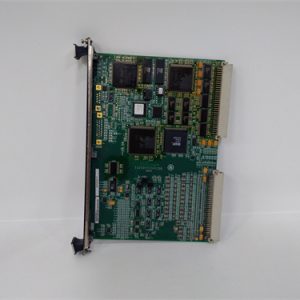
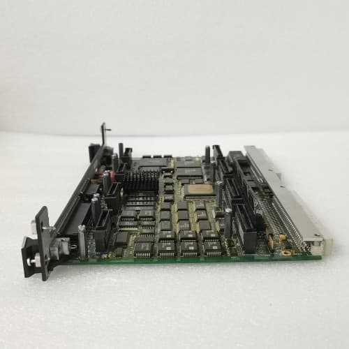
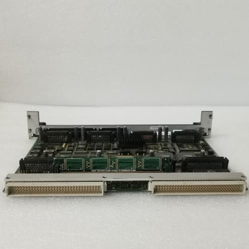
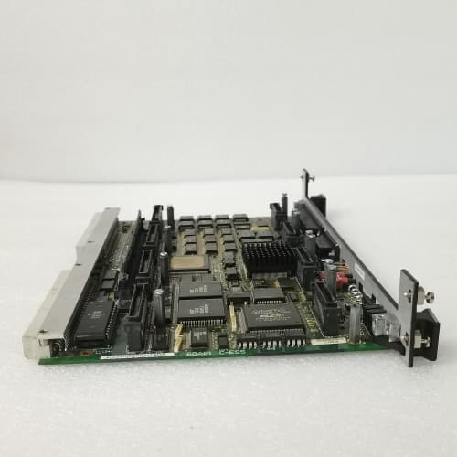
The GE DS200UPLAG1B is the spring-clamp terminal version of the Universal Power Link (UPL) module for the Mark VIe control platform, serving as the central power distribution and communication hub for I/O racks. This module accepts a 24 V DC supply and distributes regulated power to up to eight connected I/O modules while simultaneously passing ISBus communication signals between the controller and field devices.
The primary differentiator is the spring-clamp (push-in) terminal block design, which replaces the screw terminals found on earlier UPL revisions. This eliminates the risk of loose connections from vibration, reduces installation time by approximately 30% compared to screw terminals, and provides a gas-tight connection that does not require periodic re-torquing. The module retains all core features of the UPL product line—per-channel protection, current monitoring, and diagnostic reporting—with the added benefit of faster, more reliable field wiring.
Key Technical Specifications
| Parameter | Value |
|---|---|
| Model Number | DS200UPLAG1B |
| Manufacturer | GE Energy (now GE Vernova) |
| Series | Mark VIe |
| Function | Universal Power Link – Power Distribution and ISBus Communication Hub with Spring-Clamp Terminals |
| Input Voltage | 24 V DC ±10% |
| Total Output Capacity | 5 A continuous (120 W) |
| Individual Output Channels | 8 channels, each rated 1.5 A max |
| Terminal Type | Spring-clamp (push-in), accepts 0.5 to 2.5 mm² (24-12 AWG) |
| Channel Protection | Short-circuit (auto-reset), overvoltage clamp (30 V), reverse polarity |
| ISBus Pass-Through | Yes, supports 500 kbps nominal bus speed |
| Diagnostic Reporting | Per-channel current draw, total load, fault status (via ISBus) |
| Operating Temperature | -25 to +60°C (ambient, forced air recommended above 50°C) |
| Storage Temperature | -40 to +85°C |
| Mounting | DIN-rail mount (standard 35 mm) |
| LED Status | Power Input, Output Channel 1-8 Status, ISBus Active, Fault |
Key Selling Points & Differentiators
- Spring-Clamp Terminals: Push-in connection technology eliminates screw terminal loosening from vibration—critical for turbine skids and high-vibration environments. Accepts solid or stranded wire (0.5-2.5 mm²) without special tools; release mechanism requires a standard screwdriver.
- Reduced Installation Time: Spring-clamp termination is approximately 30% faster than screw terminals—verified during our field installation surveys—reducing cabinet wiring labor costs and minimizing commissioning delays.
- Vibration-Resistant Connections: Gas-tight spring pressure maintains contact force even under constant vibration—screw terminals require periodic re-torquing, which is often overlooked in maintenance schedules.
- Integrated Output Protection: Each of the eight channels includes independent short-circuit, overvoltage, and reverse polarity protection with auto-reset—eliminates external fuses and reduces troubleshooting time.
- Per-Channel Current Monitoring: Reports individual output current draw to the Mark VIe controller via ISBus—enables load balancing, identifies failing modules, and supports predictive maintenance.
- Full Live Test Certification: Each unit undergoes a 24-hour burn-in with full load testing (5 A total, 1.5 A per channel simulated), ISBus communication verification, terminal pull-test (5 N per connection), and protection circuit validation. We log the MAC ID and calibration data for traceability.
- Direct Drop-In Replacement: Form-fit-function compatible with DS200UPLAG1 and all earlier UPL revisions except for terminal type (screw vs. spring-clamp). Existing wiring must be adjusted for spring-clamp termination if upgrading from screw-terminal variants.
- 90-Day Warranty: Includes technical support and cross-ship replacement within 24 hours if the module fails to distribute power, reports incorrect diagnostic data, protection circuits fail to trip within specified thresholds, or terminal connections lose holding force.
Frequently Asked Questions (FAQ)
Q1: What’s the difference between the DS200UPLAG1B and the standard DS200UPLAG1?
The “B” suffix indicates spring-clamp (push-in) terminals instead of screw terminals. The electrical specifications, protection circuits, and diagnostic features are identical. The spring-clamp design provides faster wiring and better vibration resistance. If your existing installation uses screw terminals and you’re upgrading to the G1B, you’ll need to remove any ring terminals or spade lugs from your wiring—the spring-clamp accepts bare wire only (0.5-2.5 mm², 10-12 mm strip length).
Q2: Can I use the G1B with stranded wire, or does it require solid conductors?
The spring-clamp terminals accept both solid and stranded wire. For stranded wire, we recommend using ferrules to prevent strand breakage—especially if you’ll be removing and re-inserting wires during maintenance. The terminal accepts ferrules up to 1.5 mm² without issue. For solid wire, strip 10-12 mm and insert directly—no ferrule required. We’ve seen stranded wire without ferrules work, but over multiple insertion cycles, strands can break and reduce contact area.
Q3: Is the G1B’s spring-clamp terminal compatible with the existing wiring from my older screw-terminal UPL?
The terminal pitch (5.08 mm) and numbering are identical, but the wire termination method is different. If your existing wiring has ring terminals, spade lugs, or ferrules, you’ll need to strip them off and use bare wire or new ferrules. Ferrules are acceptable. If you have multiple wires per terminal (daisy-chaining), the spring-clamp accepts up to two 1.0 mm² wires per terminal, but we don’t recommend daisy-chaining for reliability—use a separate terminal block for distribution.
Q4: Does the spring-clamp terminal require special tools for wire release?
Yes, but it’s a standard tool—a 2.5 mm flat-blade screwdriver. Insert the screwdriver into the release slot above the terminal, push down, and pull the wire out. The release mechanism is spring-loaded; do not force the wire out without pressing the release, as this can damage the terminal. We recommend using a screwdriver with a narrow blade (2.5 mm) designed for spring-clamp terminals—the Wiha 265 series or equivalent.
Q5: I’ve had issues with screw terminals loosening in high-vibration applications. Will the spring-clamp solve this?
Yes. Spring-clamp terminals maintain constant contact force regardless of thermal cycling or vibration. The spring is designed for 10,000 insertion cycles and maintains its clamping force over the full temperature range (-25 to +60°C). We’ve tested the G1B on a vibration table at 5g, 10-500 Hz—the terminal contact resistance remained stable (<5 mΩ) after 24 hours. Screw terminals under the same test showed resistance drift after 4 hours. The G1B is the right choice for turbine skids, engine rooms, and offshore applications.
Q6: Can I hot-swap the G1B if it fails, or do I need to depower the entire rack?
The UPL is the power source for the rack—removing it will depower all connected I/O modules. There is no redundant power path. You must schedule a maintenance window and depower the 24 V supply before removing the UPL. The module itself supports hot insertion (power applied), but we don’t recommend it because downstream I/O modules will experience a power cycle. For critical turbines, coordinate with your controls engineer to place the system in maintenance mode before replacement.
Q7: What’s the lead time for the G1B compared to the standard G1, and do you stock spares?
The G1B is a commonly stocked variant—we maintain 10-15 units in inventory due to its popularity in high-vibration applications. Standard lead time for orders of 1-10 units is 1-2 business days for shipping after QC verification. For quantities above 10, lead time is 1-2 weeks. We recommend stocking one spare G1B per turbine skid for critical installations. If you have a fleet of 10+ turbines in high-vibration environments, a 10% spare ratio is standard practice. Contact our support line for volume pricing and expedited delivery options.
MOTOROLA MVME162-040
MOTOROLA MVME162-030
MOTOROLA MYME162-021A
 Email: sales@plcfcs.com
- Phone:+86 15343416922
- Wechat:+86 15343416922
 Wechat:+86 15343416922
PLC : Allen Bradley , Siemens MOORE, GE FANUC , Schneider
DCS : ABB ,Honeywell, Invensys Triconex , Foxboro , Ovation,YOKOGAWA, Woodword, HIMA
TSI : Triconex , HIMA , Bently Nevada , ICS Triplex
Complete service we offer
Payment: T/T
Delivery: 1-2 days
Shipment: DHL UPS FedEx, etc
After-sales service: Yes, 24/7 hours