 Email: jiedong@sxrszdh.com
 Phone / Wechat:+86 15340683922
Description
Product Introduction (Anti-Template)
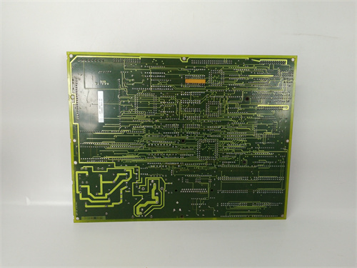
The DS200TCTEG1A is a high-density thermocouple input board—the board that converts thermocouple signals (J, K, T, E, N, R, S, B) into temperature values for turbine monitoring and control. This board gives you 16 thermocouple inputs in one VME slot, with per-channel cold junction compensation, 16-bit resolution, diagnostic LEDs per channel, and improved accuracy.
The ‘TCTE’ in the part number indicates this is a thermocouple input board. The ‘A’ revision adds diagnostic LEDs per channel, improves accuracy from ±0.5°C to ±0.4°C, and improves the update rate from 20ms to 15ms. The board is designed for applications where you need many thermocouple inputs in a single slot—like monitoring multiple bearing temperatures, exhaust temperatures, or process temperatures on a large turbine skid.
Key Technical Specifications
| Parameter | Value / Range |
|---|---|
| Manufacturer | General Electric (GE) |
| Part Number | DS200TCTEG1A |
| Board Type | Thermocouple Input Board |
| Number of Channels | 16 (thermocouple inputs) |
| Input Range | ±100mV (typical thermocouple range) |
| Thermocouple Types | J, K, T, E, N, R, S, B (configurable per channel) |
| Resolution | 16-bit (65535 counts) |
| Accuracy | ±0.4°C total (including CJC, linearization) |
| Temperature Drift | ±30ppm/°C |
| CJC Method | Per-channel CJC (±0.15°C sensors) |
| Diagnostic LEDs | Per-channel: green (normal), amber (warning), red (fault) |
| Input Impedance | >10MΩ |
| Common Mode Rejection | 100dB (DC to 60Hz) |
| Isolation | Channel-to-channel: 1500Vrms; channel-to-backplane: 1500Vrms |
| Update Rate | 15ms (all channels sampled simultaneously) |
| Input Power | 24 or 48 VDC (via backplane) |
| Mounting | VME rack (fits standard Mark VI backplane) |
| Operating Temp | 0°C to +55°C |
| Firmware | Version 3.0 or later required |
| Connectors | 1 x 96-pin DIN backplane connector |
Compatible Replacement Models
Replacement options depend on your channel count and accuracy requirements.
✅ Drop-in Replacement: The DS200TCTEG1 (no ‘A’) is a direct electrical drop-in—same pinout, same 16 inputs, same per-channel CJC. The differences: the base model has no diagnostic LEDs, ±0.5°C accuracy, and a slower update rate (20ms). If you don’t need diagnostics and your accuracy requirements are moderate, the base model is a cheaper option (typically 15-20% less). The ‘A’ is the enhanced version.
⚠️ Software Compatible: The DS200TCCBG1A (8 inputs, 16-bit, per-channel CJC) provides half the channels with faster update. Only use if you don’t need 16 channels.
⚠️ Software Compatible: The DS200TCCBG2A (16 inputs, 14-bit, shared CJC) provides 16 channels with lower accuracy and shared CJC. Only use if you can tolerate shared CJC.
❌ Hardware Incompatible: Any general-purpose analog input board (TCCAG1 series) uses different backplane pins and is not suitable for thermocouple signals.
Frequently Asked Questions (FAQ)
What’s the difference between the TCTEG1A and the TCTEG1?
The ‘A’ revision adds three improvements:
- Diagnostic LEDs: Per-channel status indication (green/amber/red).
- Better accuracy: ±0.4°C vs. ±0.5°C.
- Faster update rate: 15ms vs. 20ms.
The diagnostic LEDs are the key feature—you can see the status of each input at a glance without opening ToolboxST.
How do the diagnostic LEDs work on the ‘A’ revision?
Each of the 16 channels has a tri-color LED:
- Green (solid): Normal operation—signal within range.
- Amber (flashing): Warning—signal near range limit or CJC sensor issue.
- Red (flashing): Fault—open thermocouple, out of range, or channel failure.
The LEDs are visible from the front of the board without removing it from the rack.
Can I use this board with a Mark VIe controller?
No—the TCTEG1A uses the older Mark VI backplane pinout. Mark VIe uses a different assignment and typically uses the IS200TCTEG1A for thermocouple inputs. Use the Mark VIe-specific board for new installations.
How do I test this board before installation?
Testing the TCTEG1A requires checking all 16 channels:
- Visual inspection: Check for burnt components. Look for diagnostic LEDs.
- Power-up test: Apply power. All diagnostic LEDs should briefly flash during POST.
- Firmware check: Read firmware via ToolboxST—should be 3.0 or later.
- CJC test: With no thermocouple connected, read the CJC temperature for each channel. They should all match ambient within ±0.15°C.
- Input test: Apply 10.00mV to input 1—read 250°C ± 0.4°C. Repeat for inputs 1-16.
- Diagnostic LED test: Disconnect a thermocouple—LED should flash amber or red.
- Isolation test: Measure resistance between input channels—should be >10MΩ.
What’s the most common failure on this board?
Two issues specific to the thermocouple input design:
- CJC sensor drift. The CJC sensors can drift over time—symptom: a consistent offset on all channels.
- Diagnostic LED failure. The LEDs can fail after 10+ years—a failed LED doesn’t affect the measurement.
If I’m using this board in a SIL-rated safety application, what’s the recommended maintenance interval?
The thermocouple inputs, per-channel CJC, and diagnostics make this board suitable for SIL-2 applications (not SIL-3). We recommend:
- Visual inspection: Every 6 months (check diagnostic LEDs)
- Power-up test: Every 12 months
- CJC test: Every 12 months
- Input accuracy check: Every 12 months (0.4°C spec)
- Isolation check: Every 2 years
- Full calibration: Every 5 years
What’s the lead time for a replacement TCTEG1A?
These boards are moderately available:
- New surplus: 2-4 weeks.
- Refurbished: 1-2 weeks. Ensure the refurbisher tests all 16 channels.
- Used/as-is: Available, but the CJC sensors are wear items.
Is there a direct Mark VIe equivalent?
Yes—the IS200TCTEG1A (Mark VIe version). The backplane pinout is different.
What termination board should I use with the TCTEG1A?
The TCTEG1A is designed to interface with the DS200TBCEG1 (thermocouple termination board) or the DS200TBCBG1A (thermocouple termination board). The termination board provides the CJC sensors and the terminal connections. For the full diagnostic capability, use a termination board with per-channel CJC sensors.
What’s the update rate for this board?
The TCTEG1A samples all 16 channels simultaneously at 15ms intervals—67Hz update rate. This is faster than the TCCBG1A (50ms) and the base TCTEG1 (20ms).
What’s the maximum cable length for thermocouples on this board?
GE recommends a maximum of 300 feet (100 meters) for thermocouple cable runs. The limiting factor is the resistance of the thermocouple wire and the input impedance of the board (>10MΩ). For critical temperature measurements, keep cable runs as short as possible.
DSAI130D PLC DCS
CI626V1 PLC DCS
SC513
DSQC626 PLC DCS
 Email: sales@plcfcs.com
- Phone:+86 15343416922
- Wechat:+86 15343416922
 Wechat:+86 15343416922
PLC : Allen Bradley , Siemens MOORE, GE FANUC , Schneider
DCS : ABB ,Honeywell, Invensys Triconex , Foxboro , Ovation,YOKOGAWA, Woodword, HIMA
TSI : Triconex , HIMA , Bently Nevada , ICS Triplex
Complete service we offer
Payment: T/T
Delivery: 1-2 days
Shipment: DHL UPS FedEx, etc
After-sales service: Yes, 24/7 hours