 Email: jiedong@sxrszdh.com
 Phone / Wechat:+86 15340683922
Description
Product Introduction (Anti-Template)
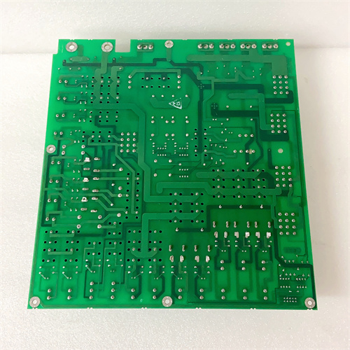
The DS200TCPDG1BDC is the absolute best programmable combined I/O board GE produced for the Mark VI system—the board that adds advanced time-stamping to the already impressive TCPDG1BCC platform. This board combines 4 programmable analog inputs with 4 programmable analog outputs (with HART) in one VME slot, with reinforced isolation (1800Vrms), extended temperature operation (-20°C to +70°C), advanced diagnostics, enhanced EMC protection (10V/m radiated immunity), advanced time-stamping for precise event correlation, and the best accuracy of any programmable I/O board.
The ‘TCPD’ in the part number indicates this is a programmable combined I/O board. The ‘BDC’ suffix tells you this is the enhanced version: 16-bit resolution on both inputs and outputs, ±0.025% input accuracy, ±0.05% output accuracy, galvanically isolated HART on outputs, reinforced isolation, extended temperature range, advanced diagnostics, enhanced EMC protection, and advanced time-stamping (±100µs accuracy). Compared to the TCPDG1BCC (0.03% inputs, 0.06% outputs), the ‘BDC’ gives you better accuracy and advanced time-stamping. If you have a compact skid with mixed sensors and actuators in a high-EMI environment and you need precise event correlation for post-event analysis, this board is the ultimate solution.
Key Technical Specifications
| Parameter | Value / Range |
|---|---|
| Manufacturer | General Electric (GE) |
| Part Number | DS200TCPDG1BDC |
| Board Type | Programmable Analog I/O Board |
| Number of Inputs | 4 (isolated analog inputs) |
| Number of Outputs | 4 (isolated analog outputs) |
| Input Range | Software-configurable per input (0-5V, 0-10V, ±10V, 4-20mA) |
| Output Range | Software-configurable per output (0-10V, ±10V, 4-20mA) |
| Input Resolution | 16-bit (65535 counts) |
| Output Resolution | 16-bit (65535 counts) |
| Input Accuracy | ±0.025% of full scale (at 25°C) |
| Output Accuracy | ±0.05% of full scale (at 25°C) |
| Temperature Drift | ±6ppm/°C (inputs), ±10ppm/°C (outputs) |
| Time-Stamping | Advanced input time-stamping (±100µs accuracy), output update time-stamping |
| Input Impedance | >5MΩ (voltage), 250Ω (current) |
| Output Impedance | <0.05Ω (voltage), >500kΩ (current) |
| Common Mode Rejection | 110dB (inputs, DC to 60Hz) |
| Diagnostic LEDs | Per-channel: green (normal), amber (warning), red (fault), blue (HART active), white (time-stamping active), flashing combinations for diagnostic codes |
| HART Support | Galvanically isolated HART modem per output channel (1800Vrms HART isolation) |
| EMC Protection | Enhanced (IEC 61000-4-3: 10V/m radiated immunity; IEC 61000-4-2: 8kV ESD; IEC 61000-4-5: 2kV surge) |
| Isolation | Channel-to-channel: 1800Vrms (reinforced); channel-to-backplane: 1800Vrms (reinforced); HART-to-analog: 1800Vrms (galvanic) |
| Update Rate | 10ms (all channels updated simultaneously) |
| Input Power | 24 or 48 VDC (via backplane) |
| Mounting | VME rack (fits standard Mark VI backplane) |
| Operating Temp | -20°C to +70°C (extended range) |
| Firmware | Version 4.7 or later required |
| Connectors | 1 x 96-pin DIN backplane connector |
Compatible Replacement Models
Replacement options depend on your need for advanced time-stamping and absolute accuracy.
✅ Drop-in Replacement: The DS200TCPDG1BCC (no ‘D’) is a direct electrical drop-in—same pinout, same 4 inputs, same 4 outputs, same programmable ranges, same HART, same isolation. The differences: the ‘BCC’ has ±0.03% input accuracy, ±0.06% output accuracy, and no time-stamping. If you don’t need time-stamping and your accuracy requirements are slightly looser, the ‘BCC’ is a cheaper option (typically 10-15% less). The ‘BDC’ is for applications requiring precise event correlation.
✅ Drop-in Replacement: The DS200TCPDG1B (no time-stamping, standard EMC) is a significant downgrade—only use if you don’t need enhanced EMC or time-stamping.
⚠️ Software Compatible: The DS200TCPAG1B (4 inputs only) provides inputs only—no outputs.
⚠️ Software Compatible: The DS200TCDAG1B (4 outputs, HART) provides outputs only—no inputs.
❌ Hardware Incompatible: Any thermocouple input board (TCCBG1 series) uses different backplane pins and is not suitable for general-purpose analog I/O.
Frequently Asked Questions (FAQ)
What does the ‘BDC’ suffix mean on this programmable combined I/O board?
GE’s suffix coding for the TCPDG1BDC: the ‘B’ is the base platform (programmable combined I/O, HART, 16-bit, ±0.04% inputs, ±0.08% outputs). The ‘D’ indicates reinforced isolation (1800Vrms), galvanically isolated HART, extended temperature range (-20°C to +70°C), enhanced EMC protection (10V/m radiated immunity), advanced diagnostics, and advanced time-stamping. The ‘C’ is the production revision with improved accuracy (±0.025% inputs, ±0.05% outputs). So ‘BDC’ is the most accurate, most noise-immune, time-stamping-enabled version of the TCPDG1 platform.
How does the advanced time-stamping work on this board?
The ‘BDC’ has a high-precision timestamping circuit that records the exact time (to ±100µs accuracy) when each analog input is sampled and when each analog output is updated. The timestamp is synchronized with the Mark VI system clock. This allows you to:
- Correlate analog input changes with turbine events
- Measure time delays in your control loops
- Perform post-event analysis with precise timing
- Validate that outputs updated when commanded
The timestamp data is available in ToolboxST and can be logged for historical analysis. The white diagnostic LED illuminates when time-stamping is active.
Can I use this board with a Mark VIe controller?
No—the TCPDG1BDC uses the older Mark VI backplane pinout. Mark VIe uses a different assignment and typically uses the IS200TCPDG1BDC for programmable combined I/O. Use the Mark VIe-specific board for new installations.
How do I test this board before installation?
Testing the TCPDG1BDC requires checking both inputs and outputs with different ranges, HART functionality, EMC protection, and timestamp accuracy:
- Visual inspection: Check for burnt components. Look for diagnostic LEDs, HART modem ICs, galvanic isolation components, EMC filtering components, and the time-stamping circuit.
- Power-up test: Apply power. All diagnostic LEDs should cycle during POST.
- Firmware check: Read firmware via ToolboxST—should be 4.7 or later.
- Input configuration test: Configure channel 1 for 0-10V. Apply 5.00V—read 5.000V ± 0.00125V (0.025%). Test at 0V, 5V, 10V.
- Input – ±10V: Configure channel 2 for ±10V. Apply -5.00V—read -5.000V ± 0.00125V.
- Input – 4-20mA: Configure channel 3 for 4-20mA. Apply 12.00mA—read 12.00mA ± 0.003mA.
- Output configuration test: Configure output 1 for 0-10V. Command 5.00V—measure 5.000V ± 0.0025V (0.05%).
- Output – 4-20mA: Configure output 2 for 4-20mA. Command 12.00mA, connect 250Ω resistor—measure 3.000V ± 0.0015V.
- Time-stamping test: Apply a known event to an input and record the timestamp. Verify accuracy within ±100µs.
- Output update time-stamping test: Command an output change and record the timestamp.
- HART test: Connect a HART device to output 1. Verify communication.
- Galvanic isolation test: Measure resistance between HART and analog circuits—should be >20MΩ.
- EMC test (if equipment available): Apply a 10V/m radiated RF field—verify outputs stay within ±0.08% of commanded value.
- Diagnostic LED test: Disconnect an input signal—LED should flash amber or red.
- Isolation test: Apply 1800Vrms for 1 minute.
- Temperature test: Cycle from -20°C to +70°C—verify accuracy stays within spec.
What’s the most common failure on the ‘BDC’ revision?
- Configuration memory corruption. The non-volatile memory that stores channel configurations can become corrupted.
- Time-stamping circuit failure. Timestamp data becomes inaccurate or unavailable.
- EMC filter component failure. Output noise increases in high-EMI environments.
- Galvanic isolation component failure. HART communication fails while analog output works.
If I’m using this board in a SIL-rated safety application, what’s the recommended maintenance interval?
The improved accuracy, galvanic isolation, reinforced isolation, enhanced EMC, and time-stamping make this board suitable for SIL-2 and SIL-3 applications. We recommend:
- Visual inspection: Every 3 months (check diagnostic LEDs)
- Power-up test: Every 6 months
- Configuration check: Every 12 months
- Input accuracy check: Every 6 months (0.025% spec—the tightest of any programmable I/O board)
- Output accuracy check: Every 6 months (0.05% spec)
- Time-stamping test: Every 12 months (verify timestamp accuracy)
- Galvanic isolation check: Every 12 months
- EMC test (if equipment available): Every 5 years
- HART test: Every 12 months
- Isolation check: Every 2 years
- Full calibration: Every 5 years
What’s the lead time for a replacement TCPDG1BDC?
These are the rarest and most advanced programmable combined I/O boards:
- New surplus: 4-8 weeks. The ‘BDC’ commands a premium—expect 25-35% above the TCPDG1BCC.
- Refurbished: 2-4 weeks. Requires specialized calibration equipment and timestamp verification.
- Used/as-is: Extremely high risk—used boards are almost never in spec.
Is there a direct Mark VIe equivalent?
Yes—the IS200TCPDG1BDC (Mark VIe version). The backplane pinout is different.
What termination board should I use with the TCPDG1BDC?
The TCPDG1BDC interfaces with the DS200TBCAG1A (general-purpose analog termination) or the DS200TBPAG1A (mixed-signal termination). For best EMC and time-stamping performance, use shielded wiring and follow the grounding instructions in the GE manual.
What’s the update rate for this board?
The TCPDG1BDC updates all 8 channels simultaneously at 10ms intervals—100Hz update rate. The timestamp is captured at the exact moment of sampling.
What’s the difference between the ‘BDC’ and the ‘BCC’ in terms of accuracy?
- ‘BCC’ version: Input accuracy ±0.03%, output accuracy ±0.06%.
- ‘BDC’ version: Input accuracy ±0.025%, output accuracy ±0.05%.
The ‘BDC’ achieves better accuracy with ultra-precision components and is the most accurate programmable I/O board GE ever produced.
FOXBORO P0900NX FBM25
FOXBORO P0900HT FBM24
FOXBORO P0900HS FBM22
 Email: sales@plcfcs.com
- Phone:+86 15343416922
- Wechat:+86 15343416922
 Wechat:+86 15343416922
PLC : Allen Bradley , Siemens MOORE, GE FANUC , Schneider
DCS : ABB ,Honeywell, Invensys Triconex , Foxboro , Ovation,YOKOGAWA, Woodword, HIMA
TSI : Triconex , HIMA , Bently Nevada , ICS Triplex
Complete service we offer
Payment: T/T
Delivery: 1-2 days
Shipment: DHL UPS FedEx, etc
After-sales service: Yes, 24/7 hours