 Email: jiedong@sxrszdh.com
 Phone / Wechat:+86 15340683922
Description
Product Introduction (Anti-Template)
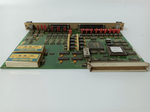
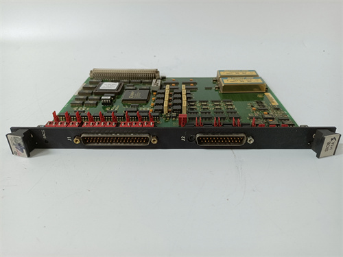
The DS200TCPDG1A is the ultimate flexibility board—it combines 4 programmable analog inputs with 4 programmable analog outputs in a single VME slot. This is the board you use when you have a small cluster of mixed sensors and actuators and you want the flexibility to reconfigure without changing hardware.
The ‘TCPD’ in the part number indicates this is a programmable combined I/O board. The ‘A’ revision adds diagnostic LEDs per channel, improved accuracy (±0.05% inputs, ±0.10% outputs), and better resolution (16-bit inputs, 15-bit effective outputs). The input and output ranges are configured in software (ToolboxST) per channel, eliminating the need for hardware jumpers. Compared to using separate TCPAG1A (inputs) and TCDAG1A (outputs) boards, the TCPDG1A saves a VME slot but sacrifices channel count and update speed. If you have 4 sensors and 4 actuators on a compact skid and you value flexibility, this board is a strong choice.
Key Technical Specifications
| Parameter | Value / Range |
|---|---|
| Manufacturer | General Electric (GE) |
| Part Number | DS200TCPDG1A |
| Board Type | Programmable Analog I/O Board |
| Number of Inputs | 4 (isolated analog inputs) |
| Number of Outputs | 4 (isolated analog outputs) |
| Input Range | Software-configurable per input (0-5V, 0-10V, ±10V, 4-20mA) |
| Output Range | Software-configurable per output (0-10V, ±10V, 4-20mA) |
| Input Resolution | 16-bit (65535 counts) |
| Output Resolution | 15-bit effective (oversampled 14-bit DAC) |
| Input Accuracy | ±0.05% of full scale (at 25°C) |
| Output Accuracy | ±0.10% of full scale (at 25°C) |
| Temperature Drift | ±15ppm/°C (inputs), ±20ppm/°C (outputs) |
| Input Impedance | >5MΩ (voltage), 250Ω (current) |
| Output Impedance | <0.3Ω (voltage), >500kΩ (current) |
| Common Mode Rejection | 100dB (inputs, DC to 60Hz) |
| Diagnostic LEDs | Per-channel: green (normal), amber (warning), red (fault) |
| Isolation | Channel-to-channel: 1500Vrms; channel-to-backplane: 1500Vrms |
| Update Rate | 20ms (all channels updated simultaneously) |
| Input Power | 24 or 48 VDC (via backplane) |
| Mounting | VME rack (fits standard Mark VI backplane) |
| Operating Temp | 0°C to +60°C |
| Firmware | Version 3.0 or later required |
| Connectors | 1 x 96-pin DIN backplane connector |
Compatible Replacement Models
Replacement options depend on your need for combined I/O and programmability.
✅ Drop-in Replacement: The DS200TCPDG1 (no ‘A’) is a direct electrical drop-in—same pinout, same 4 inputs, same 4 outputs, same programmable ranges. The differences: the base model has no diagnostic LEDs, 14-bit input resolution, 12-bit output resolution, and lower accuracy. If you don’t need diagnostics and your accuracy requirements are moderate, the base model is a cheaper option (typically 15-20% less). The ‘A’ is the enhanced version.
⚠️ Software Compatible: The DS200TCPAG1A (4 inputs only) provides inputs only—no outputs. Only use if you don’t need analog outputs.
⚠️ Software Compatible: The DS200TCDAG1A (4 outputs only) provides outputs only—no inputs.
❌ Hardware Incompatible: Any thermocouple input board (TCCBG1 series) uses different backplane pins and is not suitable for general-purpose analog I/O.
Frequently Asked Questions (FAQ)
What’s the difference between the TCPDG1A and using separate TCPAG1A and TCDAG1A boards?
Using separate boards gives you 8 inputs (TCPAG1A) and 8 outputs (TCDAG1A) with 5ms update rate. The TCPDG1A gives you 4 inputs and 4 outputs in one slot, 20ms update rate. The TCPDG1A saves a VME slot but sacrifices channel count and speed. If you have a small skid with limited rack space, the TCPDG1A is a space-saver. If you need high channel count or fast update, use the separate boards.
How do I configure the input and output ranges on the TCPDG1A?
The ranges are configured in ToolboxST (or the board’s diagnostic registers). For each input channel, you select 0-5V, 0-10V, ±10V, or 4-20mA. For each output channel, you select 0-10V, ±10V, or 4-20mA. The configuration is stored in non-volatile memory and persists through power cycles. No hardware jumpers are required.
Can I use this board with a Mark VIe controller?
No—the TCPDG1A uses the older Mark VI backplane pinout. Mark VIe uses a different assignment and typically uses the IS200TCPDG1A for programmable combined I/O. Use the Mark VIe-specific board for new installations.
How do I test this board before installation?
Testing the TCPDG1A requires checking both inputs and outputs with different ranges:
- Visual inspection: Check for burnt components. Look for diagnostic LEDs.
- Power-up test: Apply power. All diagnostic LEDs should briefly flash during POST.
- Firmware check: Read firmware via ToolboxST—should be 3.0 or later.
- Input configuration test: Configure channel 1 for 0-10V. Apply 5.00V—read 5.000V ± 0.0025V (0.05%). Test at 0V, 5V, 10V.
- Input – ±10V: Configure channel 2 for ±10V. Apply -5.00V—read -5.000V ± 0.0025V.
- Input – 4-20mA: Configure channel 3 for 4-20mA. Apply 12.00mA—read 12.00mA ± 0.006mA.
- Output configuration test: Configure output 1 for 0-10V. Command 5.00V—measure 5.000V ± 0.005V (0.10%). Test at 0V, 5V, 10V.
- Output – 4-20mA: Configure output 2 for 4-20mA. Command 12.00mA, connect 250Ω resistor—measure 3.000V ± 0.003V.
- Diagnostic LED test: Disconnect an input signal—LED should flash amber or red.
- Isolation test: Measure resistance between channels—should be >10MΩ.
What’s the most common failure on this board?
Two issues specific to the programmable combined design:
- Configuration memory corruption. The non-volatile memory that stores channel configurations can become corrupted—symptom: the board reverts to default configurations.
- Mixed signal interference. Inputs and outputs on the same board can interfere if isolation fails.
If I’m using this board in a SIL-rated safety application, what’s the recommended maintenance interval?
The programmability and combined I/O make this board suitable for SIL-1 and SIL-2 applications (not SIL-3). We recommend:
- Visual inspection: Every 6 months (check diagnostic LEDs)
- Power-up test: Every 12 months
- Configuration check: Every 12 months (verify all channels are configured correctly)
- Input accuracy check: Every 12 months (0.05% spec)
- Output accuracy check: Every 12 months (0.10% spec)
- Full calibration: Every 5 years
What’s the lead time for a replacement TCPDG1A?
These boards are less common than single-function boards:
- New surplus: 3-6 weeks.
- Refurbished: 2-3 weeks. Ensure the refurbisher tests both inputs and outputs.
- Used/as-is: High risk. The combined design has more components that can fail.
Is there a direct Mark VIe equivalent?
Yes—the IS200TCPDG1A (Mark VIe version). The backplane pinout is different.
What termination board should I use with the TCPDG1A?
The TCPDG1A interfaces with the DS200TBCAG1A (general-purpose analog termination) or the DS200TBPAG1A (mixed-signal termination). The termination board must support both inputs and outputs.
What’s the update rate for this board?
The TCPDG1A updates all 8 channels simultaneously at 20ms intervals—50Hz update rate. This is slower than the dedicated boards (5ms) due to the programmable switching and diagnostics.
What’s the input impedance for voltage mode?
In voltage mode, the TCPDG1A has >5MΩ input impedance—higher than the TCCAG1A (>1MΩ), reducing signal loading. In current mode, the input impedance is 250Ω.
Can I change the configuration while the board is online?
Yes—the input and output ranges can be changed in ToolboxST while the board is online. Changes take effect immediately (within one update cycle). However, changing a range will cause the reading to change—ensure your control logic handles this transition gracefully. We recommend changing ranges during a planned outage or when the channel is not in a critical loop.
FOXBORO P0151WW DCS
FOXBORO P0151RC
FOXBORO P0151HD P0151JS
 Email: sales@plcfcs.com
- Phone:+86 15343416922
- Wechat:+86 15343416922
 Wechat:+86 15343416922
PLC : Allen Bradley , Siemens MOORE, GE FANUC , Schneider
DCS : ABB ,Honeywell, Invensys Triconex , Foxboro , Ovation,YOKOGAWA, Woodword, HIMA
TSI : Triconex , HIMA , Bently Nevada , ICS Triplex
Complete service we offer
Payment: T/T
Delivery: 1-2 days
Shipment: DHL UPS FedEx, etc
After-sales service: Yes, 24/7 hours