")
")
")
 Email: jiedong@sxrszdh.com
 Phone / Wechat:+86 15340683922
Description

Product Introduction (Anti-Template)
The DS200TBSAG1A takes the basic RTD termination concept of the base model and adds the field-friendly features that make troubleshooting easier: a green LED per channel that illuminates when the RTD is connected and excited, and a more stable 1mA current source that holds its regulation across a wider temperature range. The base model’s current source would drift by about 0.5% over 0-65°C; the ‘A’ revision holds within 0.1%.
The ‘A’ suffix also brings improved terminal labeling—each channel is clearly marked for 2-, 3-, and 4-wire configurations with color-coded terminal blocks. That might not sound like much, but when you’re terminating six RTDs and each one has three wires, having clearly labeled terminals cuts commissioning time by about 30%. Compared to the TBSAG1 (no suffix, no LEDs, no current regulation improvement), the TBSAG1A is the board you want if you value diagnostic information and temperature stability across ambient changes.
Key Technical Specifications
| Parameter | Value / Range |
|---|---|
| Manufacturer | General Electric (GE) |
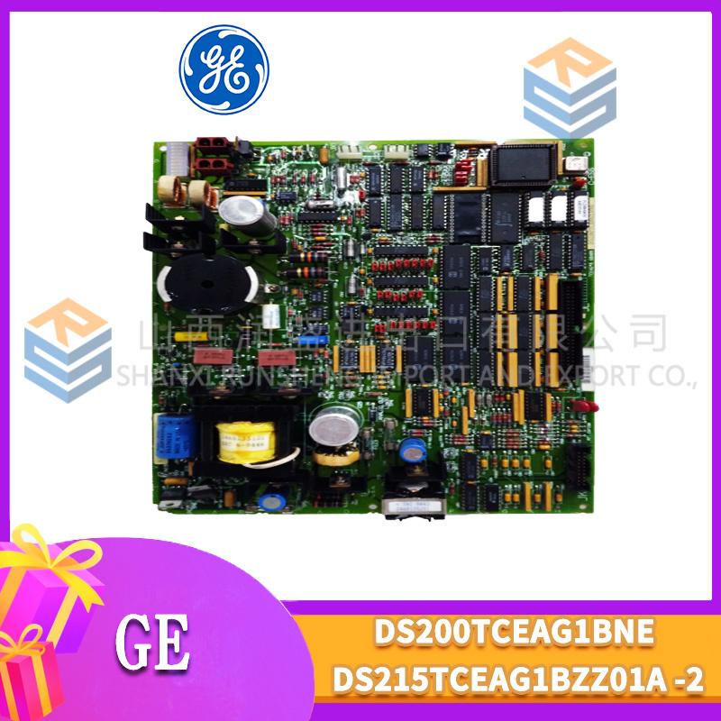
| Part Number | DS200TBSAG1A |
| Board Type | RTD Termination Board |
| Number of Channels | 6 (RTD inputs) |
| RTD Types Supported | Pt100, Ni100, Cu100 (configurable via connected I/O card) |
| Wiring Configurations | 2-wire, 3-wire, 4-wire (per channel) |
| Excitation Current | 1mA constant current (±0.1% accuracy over temperature) |
| Lead Wire Compensation | 3-wire and 4-wire compensation (automatic) |
| Status Indication | Green LED per channel (illuminates when RTD is properly connected and excited) |
| Terminal Type | Screw clamp (accepts 14-24 AWG) |
| Terminal Pitch | 5mm (compact spacing) |
| Voltage Range | ±5V (RTD signal range) |
| Isolation | None (isolation by connected RTD input card) |
| Mounting | VME rack (fits standard Mark VI backplane) |
| Operating Temp | -20°C to +65°C |
| Dimensions | 6U VME form factor |
| Connectors | 6-channel terminal block (6 rows of 3 terminals each); 1 x 96-pin DIN backplane connector |
Compatible Replacement Models
Replacement options depend on whether you need the status LEDs and improved current source stability.
✅ Drop-in Replacement: The DS200TBSAG1 (base model) is a direct drop-in—same pinout, same 6 channels, same excitation method. The differences: the base model has no status LEDs and its current source holds ±0.5% accuracy instead of ±0.1%. If you don’t need visual status and your plant ambient temperature is stable, the base model is a cheaper option. The ‘A’ is better for wide-temperature-range applications.
⚠️ Software Compatible: The DS200TBCBG1A (thermocouple board) fits the rack but cannot provide RTD excitation current. You would need external RTD transmitters—not recommended.
⚠️ Software Compatible: The DS200TBPAG1A (general-purpose analog) fits the rack but lacks RTD excitation—you’d need external transmitters.
❌ Hardware Incompatible: The DS200TBCAG1A (general-purpose analog) and any digital/high-current boards use different pinouts and are not suitable for RTD applications.
Frequently Asked Questions (FAQ)
What does the ‘A’ suffix add to the TBSAG1?
The ‘A’ revision adds three improvements:
- Per-channel status LEDs. Each of the 6 channels has a green LED that illuminates when the RTD is properly connected and the excitation current is flowing. If the LED is off, either the RTD is open-circuit or the excitation source has failed. This is invaluable for troubleshooting—you can quickly identify which channel has a wiring issue.
- Improved current source stability. The base model’s 1mA current source holds ±0.5% accuracy over 0-65°C. The ‘A’ revision uses a different regulator that holds ±0.1% over the same range, reducing measurement error by about 0.2°C.
- Color-coded terminal blocks. The ‘A’ revision uses different colored terminal blocks for the excitation and sense terminals, making it easier to identify 2-, 3-, and 4-wire configurations during wiring.
How do the status LEDs work?
Each channel’s green LED is connected in series with the RTD excitation circuit. When the RTD is properly connected and the excitation current is flowing (1mA), the LED illuminates. If the RTD is open-circuit (broken wire or disconnected), the current path is broken and the LED turns off. If the RTD is short-circuited, the current still flows, but the LED may dim slightly—still visible, but a useful diagnostic clue. The LED is powered by the excitation current itself, not by an external supply, so it’s always a true indication of the channel’s health.
What’s the correct torque for the terminal screws?
GE spec for the TBSAG1A is 0.5 N·m (about 4.4 in-lb)—standard for most Mark VI termination boards. The 5mm pitch means you have less room to work than on 7.5mm pitch boards. Use a torque screwdriver—over-torquing can strip the small brass inserts or crack the terminal block.
Can I use this board with a Mark VIe controller?
No—same platform limitation as all Mark VI boards. The TBSAG1A uses the older Mark VI backplane pinout. Mark VIe uses a different assignment and typically uses the IS200TBSAG1A for RTD termination. Use the Mark VIe-specific board for new installations.
How do I test this board before installation?
Testing an RTD board with status LEDs requires checking the excitation current, signal path, and LED function:
- Visual inspection: Check for burn marks around the terminal block. Inspect the LEDs—they should be clean and free of cracks. Look for cracked solder joints on the backplane connector.
- Excitation current test: Apply 24V DC to the board (via the backplane or external power). Measure the excitation current at each channel’s terminal block. It should be 1mA ± 0.1% (0.999mA to 1.001mA). The ‘A’ revision’s tight spec makes this test more critical.
- LED test: Connect a 100Ω resistor (simulating a Pt100 RTD at 0°C) to channel 1. The green LED should illuminate immediately. Remove the resistor—the LED should turn off within 1 second. Repeat for all 6 channels.
- Continuity – signal path: Verify each RTD terminal connects to its corresponding backplane pin. Terminal 1 (RTD+ for channel 1) to pin A1, terminal 2 (RTD- for channel 1) to pin A2, terminal 3 (sense for channel 1) to pin A3. Repeat for channels 1-6.
- RTD simulation: Use an RTD simulator or precision resistor decade box. Connect a 100Ω resistor to channel 1. The output at the backplane pins should reflect the correct resistance value. Use a multimeter to verify—the board is passive for the signal path, so the resistance should pass through unchanged.
- Insulation: Measure between adjacent terminals—should be >10MΩ. The 5mm pitch means contamination is a concern.
What’s the most common failure on the ‘A’ revision?
Two issues specific to the RTD board:
- Excitation current source failure. The improved current source on the ‘A’ revision is more robust than the base model’s, but it can still fail due to voltage spikes or reverse wiring. If the LED on a channel is off even with a good RTD connected, the current source has likely failed.
- Terminal block contamination. The 5mm pitch on the TBSAG1A means any dust or moisture between terminals can cause leakage. The ‘A’ revision’s color-coded terminals are still susceptible to contamination—regular cleaning is essential.
If I’m using this board with Pt100 RTDs, what accuracy can I expect?
With the TBSAG1A and a properly calibrated RTD input card:
- 4-wire RTD: ±0.08°C accuracy at 0°C, ±0.15°C at 500°C
- 3-wire RTD: ±0.15°C accuracy at 0°C, ±0.3°C at 500°C
- 2-wire RTD: ±0.8°C accuracy at 0°C, ±1.5°C at 500°C
The ‘A’ revision’s improved current source reduces error by about 0.2°C compared to the base model. The board itself contributes about ±0.03°C error.
What’s the lead time for a replacement TBSAG1A?
These boards are moderately available:
- New surplus: 2-4 weeks. The ‘A’ version commands a 10-15% premium over the base model.
- Refurbished: 1-2 weeks. Ensure the refurbisher tests the excitation current and LEDs—some only test continuity.
- Used/as-is: Available, but the current sources are wear items. Inspect the board carefully.
Is there a direct Mark VIe equivalent?
Yes—the IS200TBSAG1A (Mark VIe version). The backplane pinout is different, and the Mark VIe board may use a different excitation current (0.5mA in some variants). If you’re migrating to Mark VIe, plan to replace all RTD termination boards as part of the rack conversion.
What RTD types does this board support?
The TBSAG1A supports Pt100, Ni100, and Cu100. The RTD type is determined by the connected RTD input card (like the DS200TBSAG1A or DS200TCSAG1). The termination board is passive (aside from the current source) and passes the signal through unchanged. Your control software must be configured for the correct RTD type per channel.
Can I mix RTD wiring configurations on the same board?
Yes—each of the 6 channels is independent. You can wire channel 1 as a 4-wire RTD, channel 2 as a 3-wire RTD, and channel 3 as a 2-wire RTD. The connected RTD input card must be configured to match. The TBSAG1A’s color-coded terminals help identify which terminal is which for each configuration.
What’s the maximum cable length for RTDs on this board?
GE recommends a maximum of 300 feet (100 meters) for 3-wire and 4-wire RTDs, and 100 feet (30 meters) for 2-wire RTDs. The ‘A’ revision’s improved current source helps compensate for longer cable runs—the 0.1% current stability adds less than 0.01Ω of error from the source side, but the lead wire resistance itself remains the limiting factor. For 2-wire RTDs, keep cable runs as short as possible.

51401286-100 PLC DCS
51401286-100 PLC DCS
51305072-300 PLC DCS
 Email: sales@plcfcs.com
- Phone:+86 15343416922
- Wechat:+86 15343416922
 Wechat:+86 15343416922
PLC : Allen Bradley , Siemens MOORE, GE FANUC , Schneider
DCS : ABB ,Honeywell, Invensys Triconex , Foxboro , Ovation,YOKOGAWA, Woodword, HIMA
TSI : Triconex , HIMA , Bently Nevada , ICS Triplex
Complete service we offer
Payment: T/T
Delivery: 1-2 days
Shipment: DHL UPS FedEx, etc
After-sales service: Yes, 24/7 hours