")
")
")
 Email: jiedong@sxrszdh.com
 Phone / Wechat:+86 15340683922
Description

Product Introduction
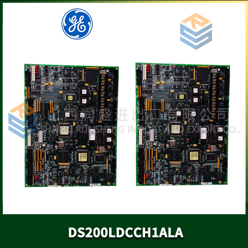
The DS200QTBAG1A is a quad-bank termination board for GE’s Mark V DS200 series, used in Speedtronic turbine control systems. It provides 32 field wiring positions arranged in four independent groups of eight channels each.
The “Q” designation indicates quad-bank (four isolated termination sections on one board). This is essentially two PTBAG1A boards integrated into a single assembly. Each of the four banks has its own 24 VDC field power bus (10 A), per-channel fusing (1 A), and status LEDs. The board connects to up to four separate I/O modules via individual ribbon cables or one 64-pin backplane connector. This is the highest-density passive termination board in the Mark V family.
Key Technical Specifications
| Parameter | Value |
|---|---|
| Number of field terminations | 32 (4 banks of 8 channels) |
| Bank A channels | 1–8 |
| Bank B channels | 9–16 |
| Bank C channels | 17–24 |
| Bank D channels | 25–32 |
| Terminal type | Cage clamp (spring), 12–24 AWG, or screw terminal (variant dependent) |
| Fusing | Per-channel replaceable fuse, 1 A fast-blow, 5×20 mm |
| Field power buses | 4 independent buses, each 24 VDC nominal at 10 A continuous |
| Per-bank power indication | Green LED (power present) |
| Per-channel signal indication | Optional LED (jumper-selectable) |
| Isolation (bank-to-bank) | 1500 VAC for 1 minute |
| Maximum voltage any terminal | 250 VAC / 125 VDC to ground |
| Dielectric strength | 1500 VAC between banks |
| Operating temperature | −30°C to +70°C |
| Storage temperature | −40°C to +85°C |
| Connection to I/O modules | Four 16-pin ribbon cables (included) or single 64-pin backplane connector |
| Mounting | 35 mm DIN rail or panel mount (4 screws) |
| Dimensions | 280 mm x 200 mm x 45 mm |
| Accessories included | Fuse puller, 8 spare fuses (1 A), 4 spare bus fuses (10 A), labeling strips, bank ID labels |
Key Selling Points & Differentiators
- 32 channels in a single board – Four independent termination banks. Replaces two PTBAG1A boards and saves cabinet space. Ideal for high-density digital I/O applications.
- Four isolated field power buses – Each bank has its own 24 VDC bus at 10 A. Power sensors from Bank A, solenoids from Bank B, indicators from Bank C, and keep Bank D as spare. No cross-bus interference.
- Per-channel fusing with visual indicator window – Each of the 32 fuses has a transparent window. Blown fuse shows a clear gap. No meter needed for troubleshooting.
- Independent ribbon cables per bank – Wire each bank to a different I/O module (e.g., Bank A to digital input module, Bank B to digital output module). No need to route all 32 signals to a single module.
- No firmware, no configuration – Passive termination. Works with any Mark V I/O module: digital input (DS200DDCBG), digital output (DS200DACBG), analog input (DS200ADPBG), or relay output.
- QC includes bank-to-bank isolation and continuity – Every channel tested for continuity from terminal to ribbon pin. Isolation tested between all four banks at 1500 VAC.
- 2-year warranty – Covers terminal failure, fuse holder damage, trace damage, or any manufacturing defect.
Frequently Asked Questions (FAQ)
Q: What’s the difference between DS200QTBAG1A and the PTBAG1A?
A: The PTBAG1A has 64 channels (8 banks of 8?) Wait—correction: PTBAG1A has 64 channels arranged as 4 groups of 16. The QTBAG1A has 32 channels arranged as 4 groups of 8. The QTBAG1A is physically smaller and designed for applications with lower channel density per I/O module. Also, the QTBAG1A uses four separate 16-pin ribbon cables (one per bank) versus one 64-pin cable on the PTBAG1A.
Q: Can I use this board with 120 VAC field signals instead of 24 VDC?
A: Yes—the terminals and fuses are rated for 250 VAC. However, the power bus LEDs are DC-only and will not light with AC. The per-channel LED option is also DC-only (requires correct polarity). For 120 VAC applications, ignore the LEDs. The board functions correctly as a passive termination panel.
Q: How do I connect the board to my I/O modules?
A: Four 16-pin ribbon cables are included. Each cable connects one bank (8 channels) to one I/O module. For example: Bank A (channels 1–8) connects to a DS200DDCBG digital input module. Bank B (channels 9–16) connects to a DS200DACBG digital output module. You can also use a single 64-pin backplane connector if your I/O module supports it (check your module’s documentation).
Q: Can I combine banks to get 24 VDC at 40 A for a single group?
A: No. The four banks are electrically isolated from each other at 1500 VAC. You cannot parallel them without defeating the isolation. If you need 40 A for a single group, use an external power distribution block. The QTBAG1A is designed for four independent loads.
Q: The board has 32 fuses. Are they all the same?
A: Yes. All 32 positions use 1 A fast-blow, 5×20 mm ceramic fuses. Spare fuses are included. For channels driving inductive loads (solenoids, relays), we recommend upgrading to slow-blow fuses (1 A, time-delay). We sell fuse kits separately.
Q: What is the maximum wire size for the field terminals?
A: Cage clamp terminals accept 12–24 AWG. For 12 AWG, strip length 8 mm (0.31 inches). We recommend ferrules for stranded wire 16 AWG and smaller. Screw terminal versions (if applicable) accept 10–24 AWG at 0.6 Nm torque.
Q: Can I mount this board vertically?
A: Yes. The cage clamp terminals hold wire in any orientation. However, the fuse holders are spring-loaded. In vertical mounting, gravity may affect fuse retention over many years. We recommend horizontal mounting when possible. For vertical mounting, use the included locking fuse holder clips (install after inserting each fuse).
Q: What QC tests do you run on the QTBAG1A?
A: Nine tests:
- Visual: Solder joints, terminal alignment, fuse holder integrity.
- Continuity: Every terminal to its ribbon cable pin. Resistance <0.1Ω.
- Bank-to-bank isolation: 1800 VAC for 5 seconds between each bank pair. Leakage <0.5 mA.
- Fuse holder grip test: Insert and remove test fuse. Extraction force 2–8 N.
- Power bus test: 24 VDC applied to each bus, 10 A load for 1 hour. Thermal camera confirms no hot spot >80°C.
- LED test (if populated): Verify each power LED illuminates at 24 VDC.
- Ribbon cable continuity: All four cables tested for shorts and opens.
- DIN rail clip test: Mount and unmount 20 times. No clip deformation.
- Vibration (sample lot): 3 Grms, 10–500 Hz, 1 hour per axis. No loose hardware.
Q: What shipping protection?
A: Anti-static bag with conductive foam. The four ribbon cables are coiled and secured with cable ties. Accessories in separate small bag. The board is large (280 mm x 200 mm), so we use a custom foam insert and double-wall box. “FRAGILE” and “ESD SENSITIVE” labels. Each board ships individually.

DS215TCEAG1BZZ01A GE
DS215DENQG3AZZ01A GE
DS215GASQG4AZZ01A GE
 Email: sales@plcfcs.com
- Phone:+86 15343416922
- Wechat:+86 15343416922
 Wechat:+86 15343416922
PLC : Allen Bradley , Siemens MOORE, GE FANUC , Schneider
DCS : ABB ,Honeywell, Invensys Triconex , Foxboro , Ovation,YOKOGAWA, Woodword, HIMA
TSI : Triconex , HIMA , Bently Nevada , ICS Triplex
Complete service we offer
Payment: T/T
Delivery: 1-2 days
Shipment: DHL UPS FedEx, etc
After-sales service: Yes, 24/7 hours