")
")
")
 Email: jiedong@sxrszdh.com
 Phone / Wechat:+86 15340683922
Description

Product Core Brief
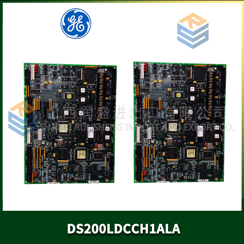
- Model: DS200QTBAG3ADC
- Brand: General Electric (GE)
- Series: Mark V DS200
- Core Function: High-density quad-bank termination with 64 channels per board
- Product Type: Termination Board / Field Wiring Panel
- Key Specs: 64 field terminations | 4 banks of 16 channels | 24 VDC @ 15 A per bus | Voltage monitoring | Alarm outputs
- Condition: New Original / Factory surplus.
Product Introduction
The DS200QTBAG3ADC is a high-capacity quad-bank termination board for GE’s Mark V DS200 series, used in Speedtronic turbine control systems. It provides 64 field wiring positions arranged as four independent banks of 16 channels each—double the channel density of the standard QTBAG1 series.
The “3” designation indicates the 64-channel variant (banks of 16 rather than 8). The “ADC” suffix adds enhanced features: 15 A per-bus continuous rating, reverse polarity protection, per-bank voltage monitoring with analog output, Form C alarm relays, lever-extraction fuse holders, and high-Tg PCB with 4 oz copper. This is the highest-density, most feature-rich termination board in the Mark V family.
Key Technical Specifications
| Parameter | Value |
|---|---|
| Number of field terminations | 64 (4 banks of 16 channels) |
| Bank A channels | 1–16 |
| Bank B channels | 17–32 |
| Bank C channels | 33–48 |
| Bank D channels | 49–64 |
| Terminal type | Heavy-duty screw clamp, rising cage, 10–24 AWG, with wire protector |
| Terminal torque | 0.6–0.8 Nm (5.3–7.1 lb-in) |
| Fusing (per channel) | Replaceable fuse, 1 A fast-blow, 5×20 mm, ceramic, lever-extraction holder |
| Field power buses | 4 independent buses, each 24 VDC nominal (18–30 VDC range) at 15 A continuous, 25 A peak (10 sec) |
| Reverse polarity protection | Schottky diode per bus, 30 V reverse withstand, 40 A surge rating |
| Per-bank voltage monitoring | Analog output 0–10 VDC = 0–30 VDC field bus voltage, accessible via test points |
| Per-bank alarm output | Form C relay (rated 1 A @ 24 VDC) triggers when bus voltage <20 VDC or >28 VDC |
| Per-bank power indication | Green LED (power present), Red LED (reverse polarity), Yellow LED (voltage out of range) |
| Per-channel signal indication | Optional LED (high-brightness), jumper-selectable polarity |
| Isolation (bank-to-bank) | 1500 VAC for 1 minute, leakage <1 mA |
| Isolation (input-to-ground) | 1500 VAC for 1 minute |
| PCB material | High-Tg FR-4, Tg 170°C, 4 oz copper on power planes, aluminum backing on bus bars |
| Operating temperature | −40°C to +75°C |
| Storage temperature | −40°C to +90°C |
| Connection to I/O modules | Four 16-pin ribbon cables (included, shielded, 1 meter each) for each bank? Note: 4 banks x 16 channels requires 4 separate 16-pin cables or 2 x 32-pin configurations—verify |
| Backplane connection | Optional 64-pin DIN 41612 |
| Monitoring output connector | 9-pin D-sub (female, included cable) |
| Mounting | 35 mm DIN rail with locking clips (included) or panel mount (8 screws) |
| Dimensions | 350 mm x 250 mm x 55 mm |
| Weight | 2.8 kg (6.2 lbs) |
| Accessories included | Lever fuse puller, 16 spare fuses (1 A), 4 spare bus fuses (15 A slow-blow), 9-pin D-sub cable (1 m), labeling strips (1–64), bank ID labels, torque card, mounting hardware, end clips (4) |
Key Selling Points & Differentiators
- 64 channels on one board – Four banks of 16 channels each. Highest density termination board for Mark V. Replaces two QTBAG1ADC boards or four PTBAG1A boards. Saves significant cabinet space.
- 15 A per bank with reverse polarity protection – Each of the four banks delivers 15 A continuous. Schottky diodes prevent damage from miswired supplies. Red LED indicates reverse polarity.
- Per-bank voltage monitoring with alarm relay – Analog output (0–10 VDC = 0–30 VDC bus voltage) and Form C relay per bank. Relay trips on undervoltage (<20 VDC) or overvoltage (>28 VDC). Connect to PLC for remote diagnostics.
- Lever-extraction fuse holders on all 64 channels – No tools required. Lift lever, fuse pops out. Replace, push lever down. Rated for 1,000 cycles.
- High-Tg PCB with 4 oz copper and aluminum bus bar backing – Handles 15 A continuous per bank with 35°C temperature rise. Aluminum backing under power traces acts as heat spreader. Standard boards without backing would run at 70°C rise.
- Per-bank yellow LED out-of-range indicator – Lights when bus voltage drops below 20 VDC or exceeds 28 VDC. Instant visual warning before relay trips.
- Shielded ribbon cables included for all banks – Four shielded 1-meter 16-pin ribbon cables reduce EMI pickup on long runs.
- QC includes 4-hour full load thermal imaging on all four banks simultaneously – 15 A on each bank (60 A total across the board) for 4 hours. Thermal camera verifies no hot spot exceeds 90°C. You receive thermal images.
- 2-year warranty – Covers all channels, monitoring circuits, reverse polarity survival, and any manufacturing defect.
Frequently Asked Questions (FAQ)
Q: What’s the difference between QTBAG1ADC and QTBAG3ADC?
| Feature | QTBAG1ADC | QTBAG3ADC |
|---|---|---|
| Total channels | 32 | 64 |
| Banks | 4 banks of 8 | 4 banks of 16 |
| Per-bus current | 15 A | 15 A |
| Dimensions | 280 x 210 mm | 350 x 250 mm |
| Weight | 2.1 kg | 2.8 kg |
| Ribbon cables | 4 x 16-pin | 4 x 16-pin (or optional 2 x 32-pin) |
The 3ADC has double the channel density in the same quad-bank architecture. Choose 3ADC when you need 64 terminations in one board.
Q: Can I replace two QTBAG1ADC boards with one QTBAG3ADC?
A: Yes, electrically. The pinout per bank is identical. However, the physical layout of field terminals changes—bank A on the 3ADC has 16 terminals (1–16) versus 8 terminals (1–8) on the 1ADC. You will need to re-land field wires. Plan for 4–6 hours of re-termination work. The ribbon cable connections to I/O modules are the same (16-pin per bank).
Q: How do I connect 64 channels to I/O modules?
A: The QTBAG3ADC has four independent 16-pin ribbon cable connectors (one per bank). Each 16-pin cable connects to one 16-channel I/O module (e.g., DS200DDCBG digital input). You need four I/O modules to utilize all 64 channels. Alternatively, you can use two 32-channel I/O modules if available (check your Mark V configuration).
Q: The board has 64 fuses. Are they all the same?
A: Yes. All 64 positions use 1 A fast-blow, 5×20 mm ceramic fuses. Spare fuses (16) are included. For inductive loads (solenoids, relays), upgrade to slow-blow fuses (1 A time-delay). We sell fuse kits in quantities of 50, 100, and 500.
Q: What is the maximum current draw if all 64 channels are active?
A: Each channel is fused at 1 A, but the bus is limited to 15 A per bank. Therefore, per bank, the sum of all channel currents cannot exceed 15 A. With 16 channels per bank, the average per channel is 0.94 A. If you need more than 15 A total per bank, use an external power distribution block. The QTBAG3ADC is designed for typical I/O loads (sensors, indicator lights, small relays), not high-current solenoids.
Q: The board is large and heavy (2.8 kg). Will DIN rail hold it?
A: Yes, but with precautions. Use steel DIN rail (35 mm x 7.5 mm, EN 50022). Do not use aluminum or plastic rail. Install end clips on both sides of the board (four clips total—two on each end). For high-vibration environments, we strongly recommend panel mounting using the eight M4 screw holes. Panel mounting brackets and screws are included.
Q: Can I use this board with 48 VDC field devices?
A: No. The bus inputs are rated for 18–30 VDC continuous. The monitoring circuit alarms at 30 VDC and relays de-energize at 30 VDC. Applying 48 VDC will destroy the monitoring circuit. For 48 VDC applications, use the QTBAG3A (base version, no monitoring) with external voltage reduction.
Q: What is the accuracy of the voltage monitoring output?
A: ±2% of reading from 0–30 VDC bus voltage. Output is 0–10 VDC linear. Formula: Bus Voltage = V_MON × 3. Calibrated at the factory with a NIST-traceable meter. Recalibration recommended every 5 years. We offer recalibration service for $85 per board.
Q: What QC tests are specific to the QTBAG3ADC?
A: Twelve tests, all documented:
- Visual: 20x magnification of all 64 fuse holder solder joints and power bus connections.
- Continuity: Every terminal (64 channels) to its ribbon pin. Resistance <0.05Ω.
- Bank-to-bank isolation: 1800 VAC for 5 seconds between all bank pairs (6 combinations). Leakage <0.5 mA.
- Reverse polarity test per bank: −30 VDC applied. Verify red LED, zero current >20 mA.
- Voltage monitoring accuracy per bank: Apply 0 V, 10 V, 20 V, 24 V, 30 V. Measure V_MON output. Error <±2%.
- Alarm relay test per bank: Ramp voltage from 0 V to 30 V. Verify energize/de-energize points. Hysteresis <2 V.
- Fuse holder lever test: 20 cycles per holder (sample of 16 positions). Extraction force 3–8 N.
- Full load thermal: 15 A on each of 4 banks simultaneously (60 A total) for 4 hours. Thermal image every hour. No hot spot >90°C.
- Overload: 25 A peak for 10 seconds, 10 times per bank. Trace temperature rise <50°C.
- Ribbon cable test: All four shielded cables tested for continuity, shorts, shield continuity, and capacitance (<100 pF).
- DIN rail clip test: Mount and unmount 50 times. No clip deformation.
- Vibration (sample lot): 5 Grms, 10–500 Hz, 2 hours per axis. No loose hardware, no fuse holder opening.
Q: What shipping protection for this large heavy board?
A: Maximum protection. First: anti-static bag with humidity indicator. Second: custom-molded ESD foam cradle with cutouts for all 64 fuse holders, four ribbon cable connectors, and D-sub connector. Third: hard plastic clamshell case with foam liner. Fourth: double-wall corrugated box with “PRECISION INSTRUMENT,” “CALIBRATION INCLUDED,” “HEAVY” (2.8 kg), “DO NOT STACK,” and “THIS SIDE UP” labels. Shock indicator and tilt indicator labels on outside. Each board ships individually. The four ribbon cables and D-sub cable ship in separate anti-static bags inside the same box. Calibration certificate laminated and attached to outside of clamshell. Desiccant pack included.

DS200CTBAG1ACC GE
DS200TBQCG1AAA
DS200TCQAG1BFE GE
DS200TCQAG1BED GE
 Email: sales@plcfcs.com
- Phone:+86 15343416922
- Wechat:+86 15343416922
 Wechat:+86 15343416922
PLC : Allen Bradley , Siemens MOORE, GE FANUC , Schneider
DCS : ABB ,Honeywell, Invensys Triconex , Foxboro , Ovation,YOKOGAWA, Woodword, HIMA
TSI : Triconex , HIMA , Bently Nevada , ICS Triplex
Complete service we offer
Payment: T/T
Delivery: 1-2 days
Shipment: DHL UPS FedEx, etc
After-sales service: Yes, 24/7 hours