
")
")
")
 Email: jiedong@sxrszdh.com
 Phone / Wechat:+86 15340683922
Description

Product Introduction
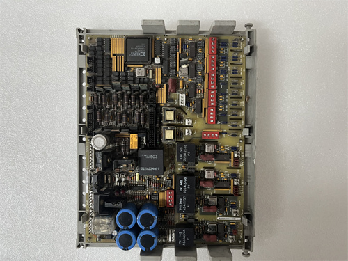
The DS200RTBAG1A is a relay output termination board for GE’s Mark V DS200 series, used in Speedtronic turbine control systems. It provides 16 independent relay outputs for driving field devices such as solenoid valves, alarm annunciators, motor contactors, and indicator lights.
Unlike generic relay boards, the RTBAG1A integrates directly with Mark V digital output modules via a 64-pin backplane or ribbon cable. Each relay is Form C (SPDT) with normally open and normally closed contacts, rated at 5 A. Per-channel LEDs indicate coil status (energized/de-energized). The board includes flyback diode protection for inductive loads and removable terminal blocks for easy field wiring replacement.
Key Technical Specifications
| Parameter | Value |
|---|---|
| Number of relay outputs | 16 |
| Relay type | Electromechanical, Form C (SPDT) |
| Contact arrangement | Common (C), Normally Open (NO), Normally Closed (NC) |
| Contact rating (resistive) | 5 A @ 250 VAC, 5 A @ 30 VDC |
| Contact rating (inductive) | 2 A @ 250 VAC (cosφ = 0.4), 2 A @ 30 VDC (L/R = 40 ms) |
| Maximum switching voltage | 250 VAC, 125 VDC |
| Maximum switching current | 5 A |
| Maximum switching power | 1250 VA, 150 W |
| Coil voltage | 24 VDC nominal (from backplane) |
| Coil current per relay | 15 mA typical at 24 VDC |
| Total backplane current | 240 mA (all 16 relays energized) + 50 mA for logic = 290 mA max |
| Coil suppression | Flyback diode (1N4007) across each coil |
| Per-channel indication | Red LED (illuminates when relay coil is energized) |
| Contact material | Silver alloy (AgNi) |
| Mechanical life | 20,000,000 operations (no load) |
| Electrical life | 100,000 operations at rated load |
| Operating time (coil to contact) | 10 ms typical |
| Release time | 5 ms typical |
| Bounce time | 3 ms typical |
| Isolation (coil to contacts) | 1500 VAC for 1 minute |
| Isolation (contact to contact) | 1000 VAC for 1 minute |
| Terminal type | Removable pluggable terminal blocks, 12–24 AWG (3 per relay: C, NO, NC) |
| Connection to output module | 64-pin ribbon cable (included) or direct backplane |
| Operating temperature | −30°C to +65°C |
| Storage temperature | −40°C to +85°C |
| Dimensions | 280 mm x 160 mm x 50 mm |
| Accessories included | Removable terminal blocks (16 sets, pre-installed), spare fuses (none—no fuses on outputs), labeling strips, relay identification card |
Key Selling Points & Differentiators
- 16 Form C relays with replaceable terminal blocks – Each relay has three screw terminals (C, NO, NC) on a removable plug. Replace a damaged block without unwiring the entire board.
- Per-channel LED for visual status – Red LED lights when the output module energizes the relay coil. Instant confirmation without a meter.
- Flyback diode protection on every coil – Suppresses voltage spikes from inductive load switching. Protects the Mark V output module from back-EMF damage.
- Pluggable terminal blocks included – All 16 terminal blocks are pre-installed. Spare blocks available separately. Wiring replacement takes minutes instead of hours.
- No external power supply needed – Coils are powered directly from the Mark V backplane (24 VDC). No additional field power required for relay operation (field power is for contacts only).
- QC includes all 16 relays cycled 100 times – Each relay is energized and de-energized 100 times on the test rack. Contact resistance measured before and after (<100 mΩ). Coil current verified at 15 mA ±2 mA.
- 2-year warranty – Covers relay contact welding, coil failure, LED failure, or any manufacturing defect.
Frequently Asked Questions (FAQ)
Q: What’s the difference between DS200RTBAG1A and the older RTBAG1 (non-A)?
A: The “A” revision adds two improvements. First: removable terminal blocks (original had fixed screw terminals). Second: upgraded relay sockets with gold-flashed contacts (original used tin-plated). Gold flashing prevents oxidation in low-current applications (<50 mA). If you’re switching dry contact signals (e.g., PLC inputs), the A revision is more reliable.
Q: Can I replace a failed relay on this board, or do I replace the whole board?
A: Individual relays are soldered to the PCB, not socketed. Replacement requires desoldering. We offer relay replacement service ($18 per relay + return shipping). For most plants, replacing the entire board is faster and more cost-effective. We keep RTBAG1A boards in stock for overnight shipping.
Q: What is the maximum inductive load I can switch?
A: At 250 VAC, 2 A with power factor 0.4 (typical for solenoid valves). At 30 VDC, 2 A with L/R = 40 ms (typical for DC contactors). For larger inductive loads, use an external interposing relay or contactor. The internal relay contacts will wear out prematurely if you exceed these ratings. We’ve seen failures in 10,000 cycles instead of 100,000.
Q: The LED is on but the field device does not operate. How do I troubleshoot?
A: Three possibilities. First: the relay coil is energized (LED on) but contacts may be welded or pitted. Measure continuity across C and NO (normally open) with power off. Resistance should be <0.5Ω. Second: field wiring loose at the removable terminal block. Third: field power supply missing (contacts switch external power—they do not supply it). The RTBAG1A does not source 24 VDC to field devices; it only closes contacts.
Q: Can I use this board for both AC and DC loads on the same board?
A: Yes. Each relay is isolated. Relay 1 can switch 120 VAC to a motor starter while Relay 2 switches 24 VDC to a solenoid. No restrictions. However, maintain proper separation of AC and DC wiring in the cabinet per local electrical codes.
Q: How do I remove the terminal blocks for wiring?
A: Each terminal block has two small latches on the sides. Squeeze gently and pull straight up. The block has 3 positions (C, NO, NC). Replacement blocks are polarity-neutral—install in any orientation. We sell spare blocks in packs of 5 (part ACC-RTB-BLOCK).
Q: What is the contact resistance spec, and how do I test it?
A: New relays: <50 mΩ. End of life (100,000 cycles at rated load): <100 mΩ. Test with a four-wire milliohmmeter. Do not use a standard multimeter—lead resistance will give false readings. Our QC report includes contact resistance measurements for all 16 relays at 100 mA test current.
Q: What QC tests do you run on the RTBAG1A?
A: Nine tests, all documented:
- Visual: Solder joints, relay seating, terminal block latch operation.
- Coil resistance: 1.6 kΩ ±5% at 25°C (15 mA at 24 VDC).
- Coil current: Energize each relay at 24 VDC, measure current. 15 mA ±2 mA.
- Contact resistance (NO and NC): Measure at 100 mA, 4-wire. <50 mΩ.
- Isolation coil-to-contacts: 1800 VAC for 5 seconds. Leakage <0.5 mA.
- Isolation contact-to-contact (within same relay): 1200 VAC for 5 seconds.
- Operate test: Cycle each relay 100 times at 1 Hz. Monitor contact closure with oscilloscope. Verify operate time <15 ms, release time <10 ms, bounce <5 ms.
- Load test (sample of 4 relays): 5 A resistive at 30 VDC, 10,000 cycles. Contact resistance after test <100 mΩ.
- LED test: Verify red LED illuminates at 24 VDC coil energization.
Q: What shipping protection?
A: Anti-static bag with conductive foam. The removable terminal blocks are shipped installed to protect the pin headers. Box with “FRAGILE” and “ESD SENSITIVE” labels. Each board ships individually to prevent bending of the terminal block pins. Accessories (spare blocks, labels) in separate small bag inside the same box.

IS215UCVEM06A GE
DS200LDCCH1A GE
IS215UCVEM09B GE
 Email: sales@plcfcs.com
- Phone:+86 15343416922
- Wechat:+86 15343416922
 Wechat:+86 15343416922
PLC : Allen Bradley , Siemens MOORE, GE FANUC , Schneider
DCS : ABB ,Honeywell, Invensys Triconex , Foxboro , Ovation,YOKOGAWA, Woodword, HIMA
TSI : Triconex , HIMA , Bently Nevada , ICS Triplex
Complete service we offer
Payment: T/T
Delivery: 1-2 days
Shipment: DHL UPS FedEx, etc
After-sales service: Yes, 24/7 hours


