 Email: jiedong@sxrszdh.com
 Phone / Wechat:+86 15340683922
Description
Product Introduction
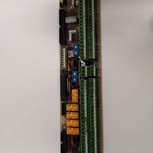
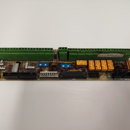
This GE 531X306LCCADM1 is a ruggedized logic and communications controller for the DC-300 and AC-300 drive platforms. The “D” in the suffix denotes differential inputs on a portion of the I/O channels. This variant is specifically designed for applications with long sensor runs or electrically noisy environments where standard single-ended inputs would false-trigger.
The board retains the same dual serial ports (RS-232 and RS-422/485), 24 configurable I/O points, and communications co-processor as the standard LCCAAM1. However, the first eight input channels are differential, providing common-mode rejection of up to ±10 V. This is critical when interfacing with proximity sensors, encoders, or limit switches located more than 100 feet from the drive cabinet, or in areas with high electromagnetic interference from VFDs, welding equipment, or heavy contactors. The board is a drop-in replacement for the standard LCCAAM1 in demanding environments.
Key Technical Specifications
| Parameter | Value |
|---|---|
| Manufacturer | GE (General Electric) |
| Model Number | 531X306LCCADM1 |
| Product Type | Logic and Communications Controller Board (Differential I/O) |
| Serial Ports | 2 (RS-232, RS-422/485) |
| Baud Rate | 300 to 38,400 bps |
| Digital I/O | 24 configurable inputs/outputs (24 VDC) |
| Input Type (Ch 1-8) | Differential, ±10 V common-mode rejection |
| Input Type (Ch 9-24) | Single-ended, 24 VDC |
| Output Drive | 0.5 A per digital output channel |
| Co-Processor | Dedicated communications processor |
| Protocol Support | GE proprietary, Modbus RTU |
| Isolation | 2500 V (opto-isolated I/O, transformer-isolated serial) |
| Communication | 50-pin ribbon cable to main regulator board |
| Operating Temperature | 0 to +55 °C |
| Storage Temperature | -40 to +85 °C |
| Board Dimensions | 12.7 in x 6.0 in (approx) |
Key Selling Points & Differentiators
- Differential Inputs on Channels 1-8: Provides ±10 V common-mode rejection, eliminating false triggers on long cable runs. This is essential for installations where standard inputs are unreliable due to electrical noise.
- Mixed Input Architecture: Get both differential and single-ended inputs on one board. Use differential for remote sensors and single-ended for local pushbuttons or selector switches. No separate signal conditioners required.
- Communications Co-Processor: Handles all serial protocol processing, offloading the main drive CPU and ensuring deterministic performance even under heavy network traffic.
- Quantified Testing Protocol: We test the differential inputs with a 60 Hz, 5 VAC common-mode signal while toggling the sensor voltage. The board must reject the noise and read the correct input state. We run this test for 30 minutes per channel.
- Warranty & Support: 2-year functional warranty. We provide a wiring diagram for differential sensor connections (three-wire sensors, shielded twisted-pair cable, drain wire termination). Differential wiring errors are the most common field mistake—our guide prevents them.
Frequently Asked Questions (FAQ)
Q1: What is the difference between the LCCADM1 and the standard LCCAAM1?
A: The “D” suffix indicates differential inputs on channels 1-8. The standard LCCAAM1 has all 24 inputs as single-ended. The differential inputs reject common-mode noise up to ±10 V, making them suitable for long sensor runs or high-EMI environments. The hardware for the differential inputs includes an additional instrumentation amplifier and a precision resistor network. The boards are mechanically identical but have a different terminal block pinout.
Q2: Can I use the differential inputs with a standard two-wire proximity sensor?
A: No. Two-wire sensors do not provide a separate return for the differential pair. For the differential inputs, you need a three-wire sensor (power, signal, and return) or a four-wire device with separate signal and return lines. If you only have two-wire sensors, use channels 9-24 (single-ended). If you need more than eight differential channels, you will need a second LCCADM1 or an external signal isolator. We recommend using Belden 8760 twisted-pair shielded cable for differential runs—it makes a measurable difference on runs over 200 feet.
Q3: I have an older system with input chatter on channel 1. Can I swap my standard LCCAAM1 for this differential board to fix it?
A: Yes, this is exactly why GE released the differential variant. The board is mechanically and electrically compatible. However, you must rewire channels 1-8 for differential connections. The terminal pinout is different—these channels now have both a signal and a return connection. You cannot just plug the board in and leave the existing wiring; you will need to pull a separate return wire for each differential sensor. We can send you the terminal wiring diagram before you order.
Q4: What is the common-mode voltage range on the differential inputs?
A: The specification is ±10 VDC common-mode at the input terminals. This means if your sensor’s return wire is floating at +5 V relative to the drive ground, the board will still read the difference correctly. Beyond ±10 V, the input protection diodes clamp and you risk damaging the input circuit. If your installation has more than 10 V of ground shift, you need an external isolation amplifier before this board. Most industrial installations with properly grounded equipment stay well within this range.
Q5: Does this board have the same serial communication capabilities as the standard LCCAAM1?
A: Yes, the serial ports are identical: one RS-232 port and one RS-422/485 port. The protocol support (Modbus RTU, GE proprietary) is the same. The communications co-processor is also identical. The only difference is the I/O front-end. The serial ports operate independently from the I/O—you can use them simultaneously without affecting the differential input performance.
Q6: What is the response time for the differential inputs compared to the single-ended inputs?
A: The differential inputs have a response time of approximately 4 µs due to the instrumentation amplifier and filter circuitry. The single-ended inputs have a response time of about 2 µs. For most applications—proximity sensors, limit switches, and photoeyes—this difference is irrelevant. However, if you are using these inputs for high-speed counting or pulse train signals above 5 kHz, the differential inputs may attenuate the signal. Use the single-ended channels for high-speed applications. We have seen customers try to use differential inputs for 20 kHz signals and encounter issues.
Q7: Does this board support Modbus RTU over the RS-485 port?
A: Yes, same as the standard LCCAAM1. The board operates as a Modbus slave on the RS-485 network. The Modbus address is set through a drive parameter. The board also supports GE’s proprietary protocol. We test Modbus RTU communication during our QC process at all supported baud rates.
Q8: What is the lifecycle status of the LCCADM1?
A: This board is rare. GE produced the differential variant in limited quantities for demanding industrial applications. We have a small batch of new surplus units available. Used pulls are uncommon because the differential circuitry is more complex and more likely to be damaged during removal. We recommend securing a spare if your application relies on the differential inputs—this board is difficult to find on the secondary market. Our new surplus units are fully tested and guaranteed.
BASLER A402KC
A-B 2711-K10G1
KONGSBERG RCU501
 Email: sales@plcfcs.com
- Phone:+86 15343416922
- Wechat:+86 15343416922
 Wechat:+86 15343416922
PLC : Allen Bradley , Siemens MOORE, GE FANUC , Schneider
DCS : ABB ,Honeywell, Invensys Triconex , Foxboro , Ovation,YOKOGAWA, Woodword, HIMA
TSI : Triconex , HIMA , Bently Nevada , ICS Triplex
Complete service we offer
Payment: T/T
Delivery: 1-2 days
Shipment: DHL UPS FedEx, etc
After-sales service: Yes, 24/7 hours