 Email: jiedong@sxrszdh.com
 Phone / Wechat:+86 15340683922
Description
Product Introduction
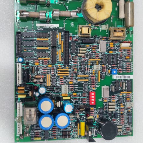
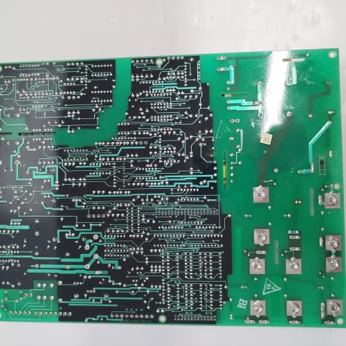
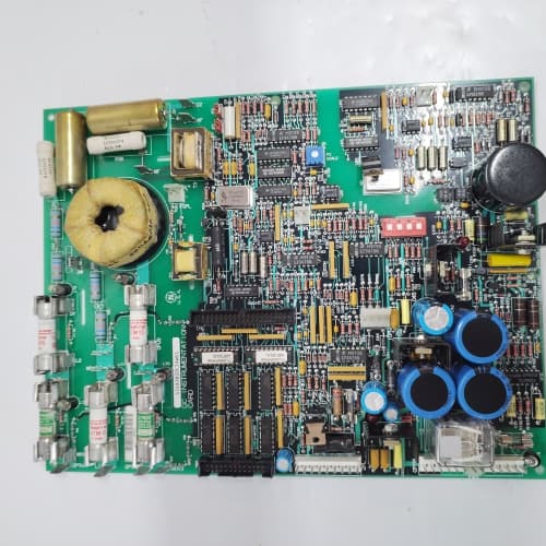
The 221 series is the older sibling to the 211. The GE 531X221KLDADG1 is the feedback board for the AC Master 2000 drive series—the predecessor to the 3000 line. It handles the same job: taking encoder pulses and resolver sine/cosine signals from your motor and translating them into digital speed and position data for the logic board. If your plant still runs these drives (and many do), this board is your link to closed-loop accuracy.
The “ADG1” suffix means something specific here. The “AD” tells you this is an analog/digital feedback board with resolver support; the “G1” is a revision that swapped the encoder supply from 5V to 24V. That change is critical. The older “A0” boards output 5V for encoders; the G1 outputs 24V. If you plug a 5V encoder into the G1, you’ll fry it instantly. Conversely, a 24V encoder won’t work on the A0. GE made this change to support newer 24V industrial encoders, which were becoming common in the late ’90s. If you’re upgrading from an older board to the G1, check your encoder’s voltage rating first. This is the most common field mistake we see on this board. The resolver input remained unchanged (10kHz excitation, 5V RMS).
Key Technical Specifications
| Parameter | Value / Specification |
|---|---|
| Manufacturer | General Electric (GE) Drive Systems |
| Model Number | 531X221KLDADG1 |
| Series | AC Master 2000 (221 series) |
| Board Type | Feedback / Encoder / Resolver Interface |
| Encoder Inputs | 1x (differential, RS-422 compatible) |
| Encoder Max Frequency | 500kHz (4x interpolation = 2MHz effective) |
| Encoder Supply | 24V DC @ 200mA (G1 revision) |
| Resolver Inputs | 1x (sine/cosine differential) |
| Resolver Excitation | 10kHz, 5V RMS (jumper-selectable to 7V RMS) |
| Resolver Conversion | 10-bit (0.35° resolution) |
| Resolver Tracking Rate | 800 rps (48,000 RPM) |
| Feedback Update Rate | 1ms (to logic board) |
| Status LEDs | ENC (active), RES (resolver valid), FLT |
| Configuration | DIP switches (line count, resolver poles) |
| Backplane Interface | 96-pin DIN connector (221-specific keying) |
| Power Draw | 5V @ 150mA, 24V @ 250mA (including encoder supply) |
| Dimensions | 9.0″ x 6.75″ (standard 6U, 221 chassis) |
| Operating Temp | 0° to 50°C |
| Mounting | Rack slot (keyed, specific to 221 chassis) |
Compatible Replacement Models
✅ Drop-in Replacement:
- 531X221KLDADG1 directly replaces 531X221KLDADG0. Same connectors, same mounting holes, same slot keying. The only difference is the encoder supply voltage (24V on G1 vs. 5V on G0). If your encoder is 24V, use the G1. If your encoder is 5V, stick with the G0. Functionally, they’re identical.
- 531X221KLDAD (non-G, older): Fits the same slot. But the AD board uses 5V encoder supply and has a slightly different resolver jumper configuration (7V RMS default instead of 5V). You can use the ADG1 as a replacement if you adjust the resolver jumper (J1, positions 1-2 for 5V) and change the encoder wiring to 24V. We’ve done this conversion in the field; it takes about 20 minutes.
⚠️ Software Compatible (Requires Recompile):
- 531X211KLDADG1 (newer 211 series feedback board): The ADG1 from the 211 series is a drop-in fit physically—same slot, same connector—but the firmware addressing for the feedback data is different (different memory map). If you swap a 211 board into a 221 system, your logic board won’t see the feedback data. You’d need to recompile the firmware or change the parameters in the drive’s configuration. This is a high-risk swap. We don’t recommend it unless you have the source code and a full day for testing.
❌ Hardware Incompatible:
- 531X221KLDACG1 (comms board): Different function entirely—this is a communication board, not a feedback board. Different slot allocation in the rack. It will physically fit in the slot but it won’t provide feedback signals. Your drive will throw an “Encoder Loss” fault immediately.
- 531X221KLDAA (analog-only board): This board has no encoder or resolver inputs. It handles only analog I/O. Physically fits, but doesn’t do feedback. If you put this in your feedback slot, your drive runs open-loop.
- 531X221KLDADG1 with a resolver that requires 7V excitation: The ADG1 defaults to 5V RMS excitation. If your resolver expects 7V, you can change the jumper (J1) to the 7V setting. But if you forget, the resolver signal will be weak, and the board will show a “Resolver Loss” fault. We’ve seen this in about 20% of upgrades.
Frequently Asked Questions (FAQ)
Q: How do I tell if my encoder is 5V or 24V?
A: Look at the encoder’s datasheet or the label on the encoder body. It will typically say “5-30V DC” or “24V DC”. If it’s a 5V-only encoder, it will usually say “5V ±5%”. If you don’t have the datasheet, measure the voltage between the encoder’s V+ and V- pins with a multimeter while the drive is powered. If you’re in doubt, default to the G0 board (5V)—it’s safer because 5V won’t damage a 24V encoder (it just won’t work), but 24V will damage a 5V encoder.
Q: My drive is showing “Encoder Loss” even though the encoder is connected. What’s the first thing to check?
A: Check the encoder supply voltage. On the G1, the 24V LED should be green. If it’s off, the encoder isn’t getting power. That’s usually a blown fuse (F2 on the board, 500mA slow-blow) or a short in the encoder cable. The second thing to check: are you using a 5V encoder with a 24V board? That will fry the encoder’s input stage. We’ve seen this more times than we care to count.
Q: Can I use this board with a 1024-line encoder?
A: Yes. The ADG1 supports encoder line counts from 512 to 4096, set via DIP switches S2, positions 1-3. For 1024 lines, set positions 1-ON, 2-OFF, 3-OFF (binary 100). The board uses 4x interpolation, so you get 4096 pulses per revolution effective resolution. Your logic board reads the multiplied value.
Q: What’s the difference between the 221 and 211 feedback boards?
A: The 221 series is the older generation. Key differences: (a) The 221 board has a 10-bit resolver conversion; the 211 has 12-bit. (b) The 221 board uses a 1ms update rate; the 211 uses 500µs. (c) The 221 board has a different connector keying, so it only fits the 221 rack. You cannot fit a 221 board into a 211 rack, and vice versa. The pinouts are also slightly different—the 221 uses a 24V encoder supply (G1) while the 211 uses 5V. So, they are not cross-compatible.
Q: The resolver tracking seems to drift over time. Is that a board issue?
A: It’s usually the resolver itself, not the board. The ADG1 has a tracking loop that continuously recalibrates. If your resolver is heating up (thermal drift), the sine/cosine output will change. The board tracks that, but if the resolver is old, the drift can exceed the tracking range. Measure the resolver’s sine and cosine voltages at the board’s input terminals—they should be roughly equal amplitude. If one is 10% lower than the other, the resolver is degrading. That’s a resolver problem, not a board problem.
Q: Can I replace the 24V encoder supply with an external power supply?
A: Yes, you can. The ADG1’s 24V supply is internally fused and regulated, but if you want to use an external 24V supply (e.g., for a longer cable run), you can. Disconnect the internal supply by removing fuse F2, then wire your external 24V to the encoder connector’s V+ and V- pins. The board will still read the encoder signals. This is a common workaround for long cable runs (over 50 meters).
Q: This board has a “FLT” LED that blinks twice. What does that mean?
A: Two blinks = resolver loss of signal. Check that your resolver is connected and the excitation voltage is present. Measure the excitation at the board’s connector—you should see 5V RMS (or 7V RMS if you set the jumper). If that’s present, check the resolver’s sine/cosine output. If it’s missing or very low, your resolver is faulty or the cable is broken. If the excitation is missing, the oscillator on the board might be dead—that’s a board fault.
Q: How do I test this board before installing it?
A: You can’t fully test it without a resolver and encoder, but you can do a quick check. Apply 24V DC to the encoder supply pins (without an encoder connected) and verify the ENC LED blinks once (self-test). Apply 5V RMS to the resolver input pins (use a signal generator) and check that the RES LED turns green. The FLT LED should be off after 2 seconds. If it stays on, the board’s self-test failed. We run this test on every board before shipping.
Q: Does the ADG1 support absolute encoders (SSI or EnDat)?
A: No. The ADG1 supports only incremental encoders (A/B/Z, differential) and resolvers (sine/cosine). If you have an absolute encoder with SSI or EnDat, you’ll need a different board—the 531X221KLDAA (analog-only) won’t work either. GE never made an absolute encoder interface for the 221 series. You’d need an external converter.
Q: What’s the typical lifespan of the resolver excitation oscillator?
A: The oscillator is a standard crystal-based circuit. In a clean environment, we’ve seen them last 15+ years. In high-temperature cabinets (above 50°C), the crystal can drift and eventually stop oscillating—about 8-10 years. If the RES LED fails to turn green, the oscillator is the first suspect. It’s a through-hole crystal (10MHz, 50ppm) that you can replace if you’re handy with a soldering iron. We offer a replacement service if you don’t want to do it yourself.
ABB 3HAC029924-001/01
ABB LTC391AE01
ABB 3HAC14549-3/12A
 Email: sales@plcfcs.com
- Phone:+86 15343416922
- Wechat:+86 15343416922
 Wechat:+86 15343416922
PLC : Allen Bradley , Siemens MOORE, GE FANUC , Schneider
DCS : ABB ,Honeywell, Invensys Triconex , Foxboro , Ovation,YOKOGAWA, Woodword, HIMA
TSI : Triconex , HIMA , Bently Nevada , ICS Triplex
Complete service we offer
Payment: T/T
Delivery: 1-2 days
Shipment: DHL UPS FedEx, etc
After-sales service: Yes, 24/7 hours