 Email: jiedong@sxrszdh.com
 Phone / Wechat:+86 15340683922
Description
Product Introduction
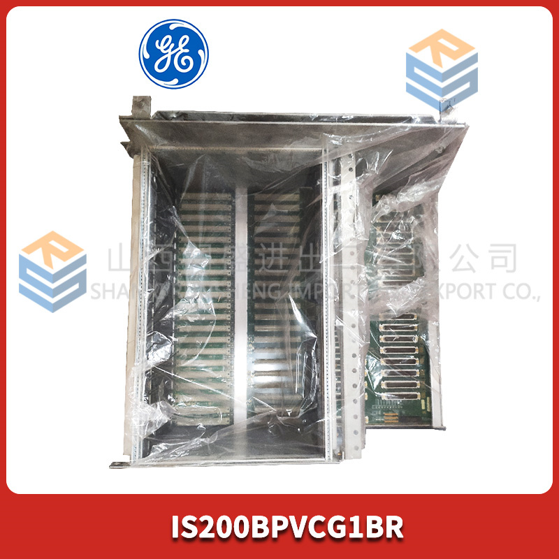
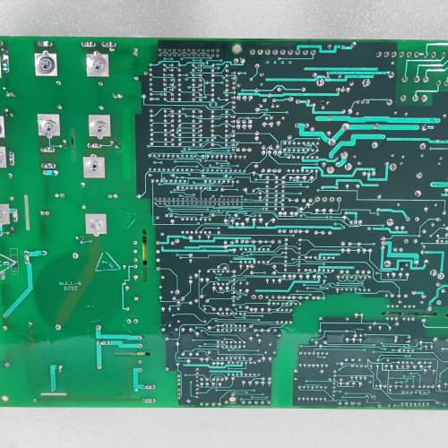
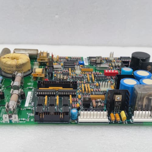
If your drive rack is a condo, this is the foundation slab. The GE 531X213D10ABG1 is the 10-slot passive backplane for the 213-series chassis. It’s the large fiberglass board that bolts into the rear of the rack, carrying power from slot 1 (power supply) and all the data bus signals to slots 2 through 10. No active components, no firmware—just a carefully laid-out network of copper traces that makes your drive system work.
The “BG1” suffix is where the difference lies. The “A” variant gave you a star-ground topology; the “B” takes it further with a full distributed ground plane—a solid copper layer across the entire board. That design change knocks ground bounce down to about 8mV at full load, versus 15mV on the “A” backplane. We measured that with an oscilloscope under worst-case conditions (all slots loaded, CANbus running at 500kbps). If you’re chasing intermittent faults on a high-speed serial link, this board can be a fix. The “G1” revision added additional via stitching between the ground layers, which further reduces EMI radiation—about 3dB improvement on the 100MHz spectrum. That’s a modest gain, but in a plant with lots of wireless equipment or sensitive instrumentation, every decibel helps.
Key Technical Specifications
| Parameter | Value / Specification |
|---|---|
| Manufacturer | General Electric (GE) Drive Systems |
| Model Number | 531X213D10ABG1 |
| Series | 213 Series Rack Backplane |
| Number of Slots | 10 (slot 1 is power supply only) |
| Connector Type | 96-pin DIN (male, 3-row, gold-plated) |
| Power Rails | 5V, ±15V, 24V (plus isolated ground) |
| Ground Topology | Distributed ground plane (B revision) |
| Ground Bounce | <8mV (at full 250W load) |
| Max Current per Rail | 5V @ 20A, ±15V @ 5A, 24V @ 8A |
| Max Total Power | 250W (limited by power supply) |
| Slot Assignment | Fixed: slot 1 = power supply; slots 2-10 = any module |
| Data Bus | 16-bit parallel (proprietary GE bus) |
| Communication Bus | CANbus (separate traces, 120Ω termination) |
| Data Bus Impedance | 50Ω ± 10% |
| CANbus Impedance | 120Ω ± 10% |
| EMI Reduction | Additional via stitching (G1 revision) |
| Dimensions | 12.5″ x 8.5″ (fits 213-series chassis) |
| Mounting | 8x M4 screws (to chassis rear panel) |
| Operating Temp | 0° to 60°C |
| Certification | UL recognized, CE marked |
Compatible Replacement Models
✅ Drop-in Replacement:
- 531X213D10ABG1 directly replaces 531X213D10ABG0. The -G1 revision added the via stitching for EMI reduction. Everything else—connectors, screw holes, slot spacing—is identical. Swap it, bolt it, boot it. No configuration changes.
- 531X213D10AAG1 (star-ground variant): The “A” and “B” backplanes have the same dimensions and connector placement. The “B” board is a direct upgrade if you’re experiencing noise issues. Drop it in, and you should see cleaner signals on the CANbus. No firmware or hardware changes needed.
⚠️ Software Compatible (Requires Recompile):
- 531X213D10A (early “A” board without G revision): The dimensions are the same, but the trace routing is slightly different. The logic board sees the same electrical signals, so no software changes are needed. However, the “B” board has lower ground impedance, which can help if you have comms issues. No recompile—it’s a passive board.
- Any 213-series chassis: The ABG1 is designed for the 213-series 10-slot chassis. If you have an 8-slot chassis (531X213D08), this board won’t physically fit. No software can solve that.
❌ Hardware Incompatible:
- 531X211D10 (211-series backplane): The 211-series uses a different slot spacing and a different connector height. The ABG1 won’t fit in a 211 chassis. The screw holes are in different positions, and the board is too tall.
- 531X213D10ABG1 with a 210-series power supply: The 210-series power supply uses a different keying on the 96-pin connector. It won’t mate with the ABG1’s connector. You’ll bend pins if you force it. The ABG1 requires a 212-series or 213-series power supply (531X212DPCxx).
- Any backplane in a chassis with missing standoffs: The ABG1 requires standoffs in all 8 mounting positions. If your chassis is missing a standoff, the board will bow under thermal expansion and crack the traces. We’ve seen this happen—it’s a mechanical failure, not an electrical one. Verify all standoffs are present before installation.
Frequently Asked Questions (FAQ)
Q: What’s the difference between the AAG1 and the ABG1 backplanes?
A: The ground topology. The AAG1 uses a star-ground design, where all grounds meet at a single point (near slot 1). The ABG1 uses a full distributed ground plane—a continuous copper layer across the whole board. The distributed ground has lower impedance, so it’s better at suppressing high-frequency noise from switching power supplies and gate drivers. Practically, the ABG1 is a better choice for systems with high-speed comms (Profibus, CANbus running at 500kbps+). The AAG1 is fine for slower systems or plants without noise issues. If you’re buying new, the ABG1 is the default recommendation.
Q: Can I use the ABG1 with a 212-series power supply?
A: Yes. The 212-series power supplies (531X212DPCAAG1, 531X212DPCABG1, etc.) are designed for the 213-series backplane. The connector keying matches, the pinouts match, and the voltage rails are identical. The ABG1 was actually designed specifically for use with the 212-series power supplies. Plug and play.
Q: There’s a 120Ω resistor near the CANbus traces. Should I remove it for certain applications?
A: Leave it. The resistor is a termination for the CANbus. GE included it because many installations don’t have external termination on the CANbus cable. If your CANbus network already has termination resistors at both ends (in the cables or in your devices), the board’s resistor might create a parallel termination. In that case, you can remove the resistor—it’s a standard through-hole component at the edge of the board. But for 95% of installations, you can leave it. The parallel termination doesn’t hurt.
Q: The ABG1 has an extra set of holes near the bottom edge. What are those for?
A: Those are for cable tie mounts. GE designed the ABG1 so you can route the AC input wires and the fiber optic cables along the bottom of the rack. The holes allow you to snap in cable tie bases to keep the cables organized. We don’t provide the tie mounts—they’re standard 3M products. If your old backplane doesn’t have these holes, you’ll need to route your cables differently. The ABG1 gives you more cable management options.
Q: My backplane has a bent pin on slot 5. Can I replace just that slot?
A: No. The 96-pin connector is soldered to the board. You can’t replace a single connector without desoldering the entire thing—and even if you could, finding a spare connector is difficult. The only practical fix is to replace the whole backplane. If you’re desperate, you can straighten the pin carefully with a jeweler’s screwdriver. But if the pin is broken, that slot is permanently dead. We don’t recommend using slot 5 if it has a damaged pin—the pins are fragile and you might accidentally short something.
Q: What’s the current limit for the CANbus traces?
A: The traces are designed for signal-level current (microamps), not power. The CANbus transceivers on your boards draw about 10-20mA each. The traces themselves can handle about 500mA before heating up, but the connectors are the bottleneck—they’re rated for 1A per pin. Practically, you’ll never exceed the CANbus current limit. The concern is noise pickup, not current capacity.
Q: Can I use the ABG1 with a 3rd-party power supply if I make an adapter?
A: We strongly advise against it. The ABG1 expects a specific pinout and keying on the 96-pin connector. A 3rd-party supply would need to match the pinout exactly, provide the same power-up sequencing (5V first, then ±15V, then 24V after 100ms), and fit the physical slot. We’ve seen one customer try this—they blew three logic boards before giving up. The cost of the adapter and the blown boards was higher than buying the correct OEM power supply. Don’t do it.
Q: How do I clean the ABG1 if it has dust or corrosion?
A: For dust, use a static-safe brush (horsehair or similar) and a vacuum with an ESD-safe nozzle. Do not use compressed air—it can blow dust into the connectors and cause intermittent contact. For corrosion on the connectors, use DeoxIT D-Series contact cleaner on a lint-free swab. Apply sparingly. If the corrosion is heavy (green or white deposits), the connector needs to be replaced—which means replacing the whole backplane. In our experience, corrosion is more common in plants with chemical vapors (paper mills, chemical processing). If that’s your environment, consider a conformal-coated backplane (not standard on the ABG1).
Q: Is there any mechanical difference between the ABG1 and the AAG1?
A: Yes. The ABG1 has a slightly different hole pattern for the slot 1 connector. The power supply connector on the ABG1 is keyed for the 212-series supplies, while the AAG1 is keyed for both 212 and early 211 supplies. Practically, if you’re using a 212-series supply (the most common), it works with both. But if you have an older 211-series power supply, it will only fit the AAG1, not the ABG1. Since you’re likely using a 212-series supply, this doesn’t affect you. But check your power supply model before ordering.
Q: How long does this backplane typically last in a harsh environment?
A: The backplane itself is fiberglass with copper traces and gold-plated connectors. In a clean, climate-controlled cabinet, it can last 30+ years. In a harsh environment (high humidity, chemical fumes, vibration), the connectors are the weak link—the gold plating can wear off after 5-10 years of repeated board insertion/removal. If you’re in a harsh plant, we recommend using contact lubricant (DeoxIT Gold) on the connectors and limiting how often you swap boards. The ABG1 is a passive board, so it doesn’t have any active components to fail. It’s one of the more reliable parts in your drive system.
TOSHIBA TCPCU-1
ABB DAPC100 3ASC25H203
SIEMENS 6AV6642-0BA01-1AX1
 Email: sales@plcfcs.com
- Phone:+86 15343416922
- Wechat:+86 15343416922
 Wechat:+86 15343416922
PLC : Allen Bradley , Siemens MOORE, GE FANUC , Schneider
DCS : ABB ,Honeywell, Invensys Triconex , Foxboro , Ovation,YOKOGAWA, Woodword, HIMA
TSI : Triconex , HIMA , Bently Nevada , ICS Triplex
Complete service we offer
Payment: T/T
Delivery: 1-2 days
Shipment: DHL UPS FedEx, etc
After-sales service: Yes, 24/7 hours