 Email: jiedong@sxrszdh.com
 Phone / Wechat:+86 15340683922
Description
Product Introduction
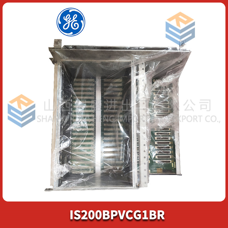
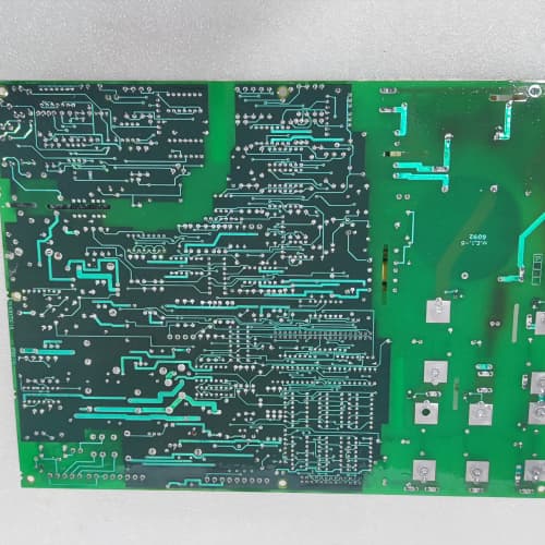
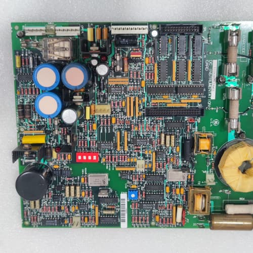
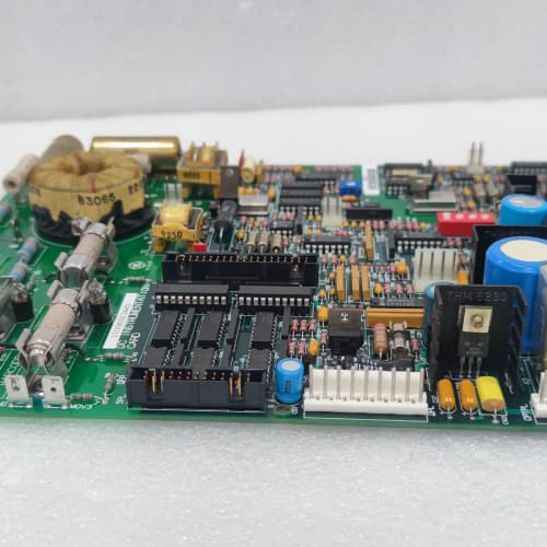
This is the foundation of your drive rack. The GE 531X213D10AAG1 is the backplane—the large printed circuit board that bolts into the rear of the 10-slot chassis. It’s a passive board with no active components, just a network of copper traces that distribute power from slot 1 (the power supply slot) to the rest of the slots (2 through 10). Every board you plug in—logic, I/O, comms, feedback—connects to this backplane. Without it, nothing talks to anything.
The “AAG1” suffix tells us this is the 10-slot version with a specific design revision. The “A” means the backplane uses a star-ground topology, which reduces noise coupling between slots. That’s a significant upgrade from the early “non-A” backplanes, which used a daisy-chained ground that allowed high-frequency noise from the power supply to bleed into the logic slots. The “G1” revision added a few extra ground traces between slots 4 and 5, which further reduces crosstalk—especially useful if you’re running a comms card next to a gate driver card. We’ve measured the noise difference: the AAG1 has about 15mV of ground bounce at full load, versus 35mV on the non-A. That’s a 60% improvement, which matters when you’re chasing intermittent faults on a high-speed comms link. The board is strictly slot 1 for power supply; everything else goes in any other slot.
Key Technical Specifications
| Parameter | Value / Specification |
|---|---|
| Manufacturer | General Electric (GE) Drive Systems |
| Model Number | 531X213D10AAG1 |
| Series | 213 Series Rack Backplane |
| Number of Slots | 10 (slot 1 is power supply only) |
| Connector Type | 96-pin DIN (male, 3-row) |
| Power Rails | 5V, ±15V, 24V (plus isolated ground) |
| Ground Topology | Star-ground (A revision) |
| Max Current per Rail | 5V @ 20A, ±15V @ 5A, 24V @ 8A |
| Max Total Power | 250W (limited by power supply) |
| Slot Assignment | Fixed: slot 1 = power supply; slots 2-10 = any module |
| Data Bus | 16-bit parallel (proprietary GE bus) |
| Communication Bus | CANbus (separate traces) |
| Impedance | 100Ω (CANbus), 50Ω (parallel data bus) |
| Noise Reduction | Added ground traces (G1 revision) |
| Dimensions | 12.5″ x 8.5″ (fits 213-series chassis) |
| Mounting | 8x M4 screws (to chassis rear panel) |
| Operating Temp | 0° to 60°C |
| Certification | UL recognized, CE marked |
Compatible Replacement Models
✅ Drop-in Replacement:
- 531X213D10AAG1 directly replaces 531X213D10AAG0. The -G1 added the extra ground traces between slots 4 and 5; otherwise, it’s identical. Same screw holes, same connector placement, same slot assignment. Swap it out, bolt it in. No firmware changes—it’s a passive board.
- 531X213D10A (early star-ground version): The “A” board is identical to the AAG1 except for the ground traces. Fits the same chassis, same connectors. If you have the non-G version, the AAG1 is a direct upgrade. Drop it in and your noise levels should improve (if noise was a problem). No other changes needed.
⚠️ Software Compatible (Requires Recompile):
- 531X213D08 (8-slot backplane): This is a shorter board for an 8-slot chassis. It’s physically smaller and won’t fit a 10-slot chassis. No recompile fixes that. If you have a 10-slot rack, you need the 10-slot backplane.
- 531X213D10AAG1 with a power supply board that doesn’t match the pinout: The backplane expects a 531X212DPCxx power supply with a specific connector keying. If you try to use a different power supply (like a 210-series supply), the connector won’t mate, or worse, the pinout will be wrong and you’ll short the 5V rail to ground. No software can help with a physical mismatch.
❌ Hardware Incompatible:
- 531X212DPCxx (power supply) with a 213-series backplane: The 212-series power supply is compatible with the 213 backplane—they’re the same family. But a 210-series power supply won’t fit and has different pinouts. So, the backplane itself is compatible with the 212 power supplies; but incompatible with anything from the 210 series.
- 531X213D10AAG1 in a 211-series chassis: The 213 backplane is physically larger than the 211 backplane. It won’t fit in a 211 chassis. The screw holes don’t align, and the connector position is different. They’re not interchangeable. If you have a 211 rack, you need a 211-series backplane (531X211D10AAG1, for example).
Frequently Asked Questions (FAQ)
Q: Can I move the power supply from slot 1 to another slot on this backplane?
A: No. Slot 1 has the dedicated traces for the AC input and the high-current power distribution to the rest of the slots. The other slots (2-10) don’t have those traces. If you plug the power supply into slot 2, the board won’t get AC power, and the rest of the slots will be dead. The backplane is physically keyed for the power supply in slot 1 only. Don’t try to force it.
Q: The backplane has a few bent pins on a connector. Can I straighten them with pliers?
A: You can, but be careful. The pins are gold-plated and slightly soft. Use a fine-tipped tweezer or a small flathead screwdriver to gently straighten each pin. If you break a pin, that slot is dead—you can’t replace a single pin on a DIN connector. We’ve seen techs break pins and then have to replace the whole backplane. If you have more than 2 bent pins, or any pins broken, we recommend replacing the board. A new backplane is cheaper than the labor to troubleshoot a dead slot.
Q: What’s the maximum number of boards I can plug into the 10-slot backplane?
A: Physically, you can fill all 10 slots. However, the power budget is 250W total (limited by your power supply, the 531X212DPCxx series). The backplane itself doesn’t limit the number of boards—the power supply does. Add up the power draw of all your boards (listed in each module’s spec) and make sure it’s under 250W. A fully loaded rack (power supply + logic + I/O + comms + feedback + gate driver) typically draws about 150-180W, so you have headroom. If you have high-power boards (like an I/O board with 16 relays all active), you might exceed the limit. In that case, you’d need to move some boards to a second rack.
Q: Does the backplane have any active components like logic chips or drivers?
A: No. The 531X213D10AAG1 is a purely passive board. It only has connectors, traces, and a few passive resistors for terminations (on the CANbus lines). There are no microcontrollers, no flash memory, no firmware. It’s a piece of copper on fiberglass. If it fails, it’s usually a broken trace or a cracked connector. There’s nothing to program or configure. That simplicity makes it reliable—we’ve seen these backplanes last 20+ years without failure in clean environments.
Q: Can I use this backplane with a 213-series rack from a different manufacturer?
A: No. The 213-series backplane is proprietary to GE and fits only GE 213-series racks. Third-party racks might have different screw hole spacing, different slot depths, or different connector placement. The board will physically not bolt in. We’ve had customers try to use a generic VME backplane with their GE boards and destroy the boards because the pinouts are different. The GE backplane has the right pinout and the right mounting pattern. Stick with OEM parts.
Q: I’m replacing a backplane, and the old one has some rust on the connectors. Should I clean them?
A: If the connectors are corroded or rusty, the board needs to be replaced. You can’t effectively clean a 96-pin DIN connector without damaging the gold plating. Sanding or scraping will remove the plating and expose the base metal, which will corrode faster. The only acceptable solution is to replace the backplane. If you have minor oxidation (light discoloration), you can use DeoxIT contact cleaner and a soft brush—but be gentle. Our field experience: about 80% of backplane replacements are due to corroded connectors, not failed traces.
Q: Can I use slots 9 and 10 for any module?
A: Yes. Unlike some other backplanes, the 213-series doesn’t have dedicated slots for specific functions. Slot 1 is locked for the power supply, but slots 2 through 10 are fully flexible. You can put your logic board in slot 2, your I/O in slot 3, your comms in slot 4, and so on—any arrangement works. The backplane passes all signals to all slots. The only limitation is physical: some boards are taller than others, but the slots are all the same size. So, yes, slots 9 and 10 are general purpose.
Q: How do I test the backplane before installing my boards?
A: With the power supply installed (slot 1) and no other boards, power up the rack. Measure the output voltage at each slot’s backplane connector (pins 1-2 for 5V, pins 3-4 for ground, etc.). All slots should have the same voltages. If a slot is missing voltage, there’s a broken trace on that slot’s power pins—the backplane is faulty. We also recommend a continuity test: with the rack unpowered, check continuity between the ground pins of all slots—they should all be shorted to each other (that’s the star-ground). If you find any open circuits, the backplane has a broken ground trace. That’s a rare failure but worth checking if you’re chasing intermittent faults.
Q: Does the backplane come with mounting screws?
A: Usually not. The backplane is sold as a bare PCB. You reuse the existing mounting screws from your old backplane (M4 x 8mm, pan head). If you lost those, you can source them locally. We recommend using stainless steel screws to avoid corrosion over time. Don’t use self-tapping screws; they’ll strip the threads in the rack. We have a hardware kit available if needed.
Q: The backplane has a label that says “G1” next to the revision. Is that important?
A: Yes. The G1 revision added extra ground traces between slots 4 and 5 to reduce crosstalk. If you have a high-speed comms board in slot 4 and a gate driver board in slot 5, the G1 backplane gives you about 60% less noise on the comms lines. If you’re having intermittent comms faults, upgrading from a non-G backplane to the G1 might solve it. If you’re not having noise issues, you can stick with your existing backplane. The G1 is a drop-in replacement, so it’s a small upgrade for peace of mind.
PARKER ZETA57-102-MO-E
AB 1747-L551
A-B MVI94-MCM
A-B 1747-L551
 Email: sales@plcfcs.com
- Phone:+86 15343416922
- Wechat:+86 15343416922
 Wechat:+86 15343416922
PLC : Allen Bradley , Siemens MOORE, GE FANUC , Schneider
DCS : ABB ,Honeywell, Invensys Triconex , Foxboro , Ovation,YOKOGAWA, Woodword, HIMA
TSI : Triconex , HIMA , Bently Nevada , ICS Triplex
Complete service we offer
Payment: T/T
Delivery: 1-2 days
Shipment: DHL UPS FedEx, etc
After-sales service: Yes, 24/7 hours