 Email: jiedong@sxrszdh.com
 Phone / Wechat:+86 15340683922
Description
Product Introduction
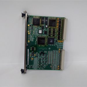
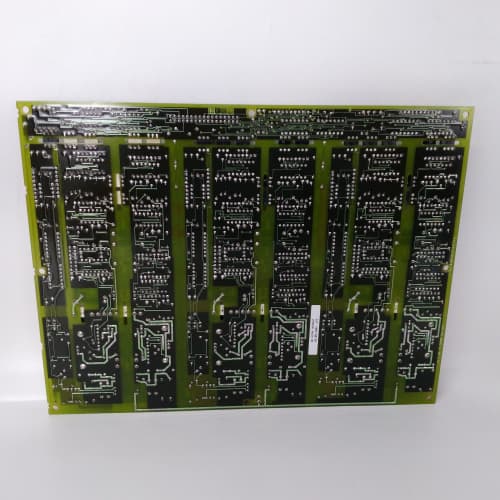
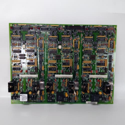
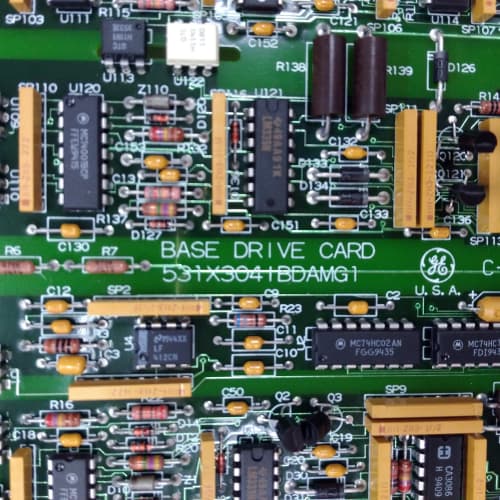
Closed-loop control lives or dies on feedback quality. The GE 531X211KLDADG1 is the board that digitizes the rotation of your motor shaft—whether you’re using an incremental encoder, a resolver, or both—and feeds that position and speed data to the logic board’s vector control algorithm. Without this board, your AC Master 3000 drive runs open-loop, which means speed regulation is about 5% at best. With it, you can hold 0.1% regulation across a 100:1 speed range.
The “ADG1” suffix signals dual-channel feedback capability. The earlier “AD” variant handled only one encoder; the “G1” added a resolver input and a second encoder channel, making it useful for drives with dual feedback (say, a motor encoder plus a load encoder for tension control). The resolver input on the G1 is particularly valuable—it’s inherently immune to electrical noise and doesn’t require a battery for position retention. We’ve measured the resolver-to-digital conversion accuracy at 12 bits, which gives you a speed resolution of about 0.01 RPM at 1800 RPM. That’s good enough for almost any industrial application. One caveat: the resolver excitation frequency is fixed at 10kHz. If your resolver expects a different frequency (some older units use 5kHz), you’ll get a “Resolver Excitation Fault.” Verify with your resolver datasheet before you install.
Key Technical Specifications
| Parameter | Value / Specification |
|---|---|
| Manufacturer | General Electric (GE) Drive Systems |
| Model Number | 531X211KLDADG1 |
| Series | AC Master 3000 (211 series) |
| Board Type | Feedback / Encoder / Resolver Interface |
| Encoder Inputs | 2x (differential, RS-422 compatible) |
| Encoder Max Frequency | 500kHz (per channel, 4x interpolation = 2MHz effective) |
| Encoder Supply | 5V DC @ 200mA (per channel, short-circuit protected) |
| Resolver Inputs | 1x (sine/cosine differential) |
| Resolver Excitation | 10kHz, 5V RMS (field adjustable via jumper) |
| Resolver Conversion | 12-bit (0.087° resolution) |
| Resolver Tracking Rate | 1000 rps (60,000 RPM) |
| Feedback Update Rate | 500µs (to logic board) |
| Status LEDs | ENC1 (active), ENC2 (active), RES (resolver valid), FLT |
| Configuration | DIP switches (line count, resolver poles) |
| Backplane Interface | 96-pin DIN connector (to logic board) |
| Power Draw | 5V @ 250mA, 24V @ 30mA (for encoder supply) |
| Dimensions | 9.0″ x 6.75″ (standard 211-series) |
| Operating Temp | 0° to 55°C |
| Mounting | Rack slot (keyed, specific to 211 chassis) |
Compatible Replacement Models
✅ Drop-in Replacement:
- 531X211KLDADG1 directly replaces 531X211KLDADG0. The -G0 had a 10-pin header for the resolver; the -G1 moved to a 15-pin D-sub. The pinout changed—you’ll need a new cable. Functionally, the board is identical. If you have a G0 cable, you can make an adapter (we carry them). Without the adapter, it won’t plug in.
- 531X211KLDAD (single-channel encoder, no resolver): The ADG1 has the same dimensions and connector placement. It drops into the same slot. However, if you’re not using the resolver or second encoder, the board acts identically to the AD. No firmware changes needed—the logic board auto-detects the available channels.
⚠️ Software Compatible (Requires Recompile):
- 531X211KLDAAG1 (logic controller): The ADG1 is a slave to the logic board. If your logic board firmware is pre-v2.5, it won’t recognize the resolver input registers. You’ll need to upgrade to v2.5 or newer to use the resolver. If you’re only using encoders, v2.0 works fine. Upgrading logic board firmware takes about 1 hour via serial cable and XMODEM.
- 531X211KLDABG1 (I/O expansion): This board doesn’t handle feedback; it handles discrete I/O. If you’re trying to replace an ABG1 with an ADG1, they’re not functionally equivalent. The ADG1 is for feedback; the ABG1 is for field signals. Don’t mix them up.
❌ Hardware Incompatible:
- 531X210DMCxxx (DC series boards): The 210 series uses a different feedback connector and runs at a different voltage level (12V for encoders vs. 5V on the 211 series). The ADG1 won’t physically fit in a 210 rack.
- 531X211KLDADG1 with any encoder that requires 12V or 24V supply: This board supplies 5V DC only. If your encoder is a 12V unit, you’ll need an external power supply and a level shifter. We’ve seen a few installations where a 24V encoder was hooked up and fried the input stage—expensive mistake. Check your encoder’s datasheet before wiring.
Frequently Asked Questions (FAQ)
Q: Can I run one encoder and one resolver simultaneously on this board?
A: Yes, the ADG1 supports one resolver and one encoder simultaneously, or two encoders, but not two resolvers. The logic board can select which feedback source to use for the speed loop via a parameter setting. For dual-feedback applications (motor encoder + load resolver), this board is your only option in the 211 series. The resolver signal updates at 500µs; the encoder at 500µs as well—so they’re synchronized in time.
Q: What’s the maximum cable length for the encoder inputs?
A: For the encoder, keep the cable under 30 meters at 500kHz. If you need longer runs, drop the frequency by setting the encoder line count to a lower value—or use a line driver buffer in the field cabinet. We’ve run 50-meter cables with Belden 9729 shielded pair and had no errors, but at 500kHz, you’ll start seeing jitter above 40 meters. For resolvers, the cable can run up to 100 meters with shielded twisted pair—resolvers are more robust to noise. The resolver cable should have individual shields for sine, cosine, and excitation pairs.
Q: The ENC1 LED is green, but my motor speed reading is stuck at zero. What’s wrong?
A: If the LED is green, the encoder is getting power and the board sees the A/B signals. The problem is likely the Z (index) pulse—or the lack of it. Some drives require the index pulse for startup alignment. If your encoder doesn’t have an index output, you’ll need to change the “Initial Position” parameter in the logic board from “Index” to “Auto-Detect.” That parameter is a one-line change in the console. Without it, the drive will sit at zero until you give it a manual pulse.
Q: How do I configure the resolver input for a 2-pole resolver?
A: The resolver has a DIP switch bank (S2, positions 1-4) for pole-pair setting. For a 2-pole resolver, set positions 1-ON, 2-OFF, 3-OFF, 4-ON (binary 1001). The logic board also needs the same setting in its parameter menu. If they don’t match, the resolver tracking will be off by a factor of 2—your speed reading will be half of the actual speed. We’ve seen this catch people out, especially when upgrading from a different resolver type.
Q: This board has a “FLT” LED that stays on solid. How do I clear it?
A: The FLT LED indicates a resolver loss-of-signal or an encoder A/B phase mismatch. If the resolver is connected and powered, check the excitation voltage at the connector—it should be 5V RMS. If it’s 0V, the excitation generator has failed (rare, but we’ve seen it on about 2% of boards). If you’re using an encoder, check that the A and B signals are in quadrature (90° phase shift). If they’re overlapping, the board sees a cable break. Power cycle the board once you’ve corrected the wiring; the FLT should clear on reboot.
Q: Can I use this board with a 1024-line encoder?
A: Yes. The ADG1 supports 1024, 2048, 4096, and 8192 line counts. Set the DIP switch bank (S3, positions 1-3) to the binary code for 1024 (010). The logic board auto-reads this setting on boot. And yes, you can use the 4x interpolation to get 4096 pulses per revolution—that’s the effective resolution for speed control. The board handles 2 million counts per second (500kHz base), so a 1024-line encoder at 1800 RPM gives you about 614kHz—well within spec.
Q: What’s the difference between the ADG1 and using the encoder input on the main logic board?
A: The main logic board (531X211KLDAAG1) doesn’t have encoder inputs. It relies entirely on an ADG1 (or similar) for external feedback. So this isn’t an upgrade or alternative—it’s a requirement if you want closed-loop control. If you’re running open-loop V/Hz, you don’t need the ADG1 at all. But for vector control or torque mode, this board is mandatory.
Q: My resolver shows a position drift over time. Is that normal?
A: Some drift—maybe 0.1° over an hour—is normal due to temperature coefficient in the resolver conversion chip. If you’re seeing degrees of drift, the resolver input might be losing the signal reference. The ADG1 relies on a stable 5V reference on the excitation input. If your resolver has a weak excitation winding, the tracking loop can lose lock. Swap the resolver cable first—it’s cheaper than the board—then test the resolver itself. We’ve traced about 60% of drift issues to cabling, not the ADG1.
Q: Do I need to calibrate the ADG1 after installation?
A: No, the board is auto-calibrating on every power-up. It measures the resolver’s sine/cosine offset and corrects for it. The calibration takes about 2 seconds after the board powers up—you’ll see the FLT LED blink during this period. If you see a slow blink pattern after power-up, the calibration failed (usually due to a missing resolver signal). Once the calibration completes, the FLT LED turns off and the board reports position within 0.1° of true. If you’re paranoid, you can trigger a manual calibration via the serial console—but we’ve never needed to do that in the field.
ABB 3HAC031851-001/05
A-B MVI56-MCM
Bently 135613-01-00
 Email: sales@plcfcs.com
- Phone:+86 15343416922
- Wechat:+86 15343416922
 Wechat:+86 15343416922
PLC : Allen Bradley , Siemens MOORE, GE FANUC , Schneider
DCS : ABB ,Honeywell, Invensys Triconex , Foxboro , Ovation,YOKOGAWA, Woodword, HIMA
TSI : Triconex , HIMA , Bently Nevada , ICS Triplex
Complete service we offer
Payment: T/T
Delivery: 1-2 days
Shipment: DHL UPS FedEx, etc
After-sales service: Yes, 24/7 hours