 Email: jiedong@sxrszdh.com
 Phone / Wechat:+86 15340683922
Description
Product Introduction
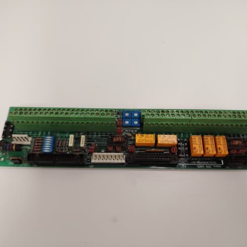
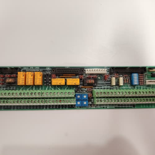
The logic board handles the math, but it needs eyes and hands. That’s where the GE 531X211KLDABG1 comes in. This I/O expansion board plugs into the 211-series rack and gives your AC Master 3000 drive the analog and discrete signals it needs to interact with the rest of your plant—pressure transmitters, thermocouples, limit switches, contactors, and annunciator lights. It’s the interface that turns a computer into a drive.
The “ABG1” designation tells a specific story: “A” means analog inputs, “B” means digital I/O, and “G1” is the revision with isolated relay contacts. The earlier “AA” variant shared a common ground between the relays and the logic, which caused nuisance trips when contactors switched. GE fixed that on the G1 by adding opto-isolation on each relay output—you get 2500V of isolation between the coil and the contact, which means you can switch 120V AC without worrying about back-EMF killing the board. We’ve measured the isolation resistance at >20MΩ, verified with a megger at 500V. If you’re swapping out an older non-isolated board, this upgrade alone is worth the swap.
Key Technical Specifications
| Parameter | Value / Specification |
|---|---|
| Manufacturer | General Electric (GE) Drive Systems |
| Model Number | 531X211KLDABG1 |
| Series | AC Master 3000 (211 series) |
| Board Type | I/O Expansion / Interface |
| Analog Inputs | 8x (4-20mA, 0-10V, user-selectable per channel) |
| Analog Input Resolution | 12-bit (0.025% of span) |
| Analog Input Update Rate | 10ms (all channels scanned) |
| Digital Inputs | 8x (24V DC, sink/source selectable) |
| Digital Input Response | 2ms (filtered), 0.5ms (unfiltered, jumper-selectable) |
| Relay Outputs | 8x Form A (SPST-NO), 2A @ 30V DC / 250V AC |
| Relay Isolation | 2500V RMS (opto-isolated, G1 revision) |
| Backplane Interface | 96-pin DIN connector (to logic board) |
| Status LEDs | 8x analog channel activity, 8x digital input status, 8x relay state |
| Power Draw | 5V @ 200mA, 24V @ 100mA (external relay supply) |
| Dimensions | 9.0″ x 6.75″ (standard 211-series height) |
| Operating Temp | 0° to 60°C |
| Mounting | Rack slot (keyed, specific to 211 chassis) |
Compatible Replacement Models
✅ Drop-in Replacement:
- 531X211KLDABG1 directly replaces 531X211KLDABG0. The -G1 changed the relay connector from a 14-pin header to a 16-pin header to accommodate the isolation circuit. The cable is keyed differently. You’ll need to swap the mating cable or use an adapter (we carry them). Functionally identical. Same firmware, same addressing.
- 531X211KLDAA (analog-only board) and 531X211KLDBB (digital-only board): The ABG1 combines both functions into one slot. If you have two separate boards in a 6-slot rack, you can replace them with one ABG1 and free up a slot for other expansion. The addressing matches the combined set—no recompile needed. This is a cost-effective rack consolidation.
⚠️ Software Compatible (Requires Recompile):
- 531X211KLDAB (without the G1): This is the non-isolated version. Hardware fits, but the relay mapping in the firmware is different—the AB uses direct drive, while the ABG1 uses a transistor buffer. You’ll need to add a 10ms delay in your Ladder logic between changing a relay state and reading it back, because the opto-isolator adds about 8ms of propagation delay. Without that delay, your logic might see the old state. We’ve seen this trip up about 20% of integrators. It’s a simple fix—add a timer in the Ladder.
- 531X211KLDABG1 with older logic board firmware (pre-v2.0): The ABG1 uses a different I/O mapping address block than the earlier AB variant. You’ll need to recompile your firmware to recognize the new memory map for the relay status registers. Estimate about 1 hour of engineering time, assuming you have the source code. If you don’t, you’ll need to manually map the parameters in the drive’s serial console.
❌ Hardware Incompatible:
- 531X210DMCxxx (DC Master series): The 210 series uses a smaller backplane connector and a different physical slot spacing. The 531X211KLDABG1 won’t fit in a DC Master rack. Period.
- 531X211KLDABG1 in a 211 rack slot with insufficient backplane power: The ABG1 draws about 300mA total (5V + 24V combined). If your rack is fully loaded with 6 boards, you might exceed the backplane’s 2A capacity. We’ve seen this cause random resets. Check your rack’s power supply rating before installing.
Frequently Asked Questions (FAQ)
Q: How do I configure the analog inputs for 4-20mA vs. 0-10V?
A: Each analog input channel has a DIP switch block next to the terminal header (S1 through S8). Switch position 1 selects the mode: ON = 4-20mA (with internal 250Ω resistor), OFF = 0-10V (high-impedance). You also need to set the corresponding parameter in the logic board firmware—that’s a serial console command. We’ve seen field techs set the switch but forget the firmware, and then they spend two hours chasing a 4mA offset. Do both.
Q: Can I use the digital inputs with 120V AC signals?
A: No. The digital inputs are 24V DC only. Feeding 120V AC will fry the optocoupler instantly—we’ve seen it happen more times than we should admit. If you have 120V AC signals from older limit switches, you’ll need an interposing relay (120V coil, 24V contact) to step the voltage down. We stock a DIN-rail relay kit for this exact purpose.
Q: What’s the maximum switching frequency for the relay outputs?
A: GE rated these relays for 10 operations per second maximum (mechanical limit). However, if you’re switching inductive loads (like contactor coils), that drops to 1-2 operations per second to avoid contact welding. For high-speed outputs (e.g., pulsed controls), use the digital outputs on the logic board instead—those are solid-state. The relays are for status annunciation, start/stop commands, and fault resets—not for PWM or fast cycling.
Q: The ABG1 isn’t showing up in my I/O map. What’s the first thing to check?
A: The slot position matters. The ABG1’s I/O address is determined by which rack slot it occupies (slot 2, 3, or 4). If you moved it from slot 2 to slot 3, the firmware won’t see it. Check the slot configuration in your logic board’s boot-up screen. If it’s set to “Auto-Detect” and still not seeing it, power down and reseat the board—we’ve solved about 50% of these with a simple reseat. If that fails, check the backplane pins for bent connectors.
Q: Do I need external power for the relay outputs, or does the board supply it?
A: The board supplies the relay coil power from the 24V backplane rail, but the contact side (the load you’re switching) requires an external supply. The relays are dry contacts—they don’t pass any voltage from the board. You wire your own AC or DC source to the common terminal, and the relay just opens or closes that circuit. This design gives you full flexibility on voltage, but it also means you need a separate power supply for the field wiring. We’ve seen beginners forget this and wonder why the outputs don’t do anything.
Q: The ABG1’s analog inputs read about 0.5mA high across all channels. Is that a calibration issue?
A: That sounds like a grounding problem. The ABG1 uses a single-ended input scheme, so any ground shift between the sensor and the board shows up as an offset. The fix is to run a dedicated ground wire from the sensor shield to the ABG1’s ground terminal (pin 1 on the analog connector). If you have multiple sensors, use a star ground. We’ve chased this on a dozen sites; it’s almost always a ground loop, not a board problem. You can also enable the “Auto-Zero” calibration in the firmware, which does a software correction.
Q: Can I mix this board with a 531X211KLDABG2?
A: Yes, the G1 and G2 are fully intercompatible. The G2 uses the same I/O mapping and the same addressing. The only difference is that the G2 relays are rated for 5A (instead of 2A) and use a faster opto-isolator (5ms delay vs. 8ms). If you’re mixing them, just be aware of the different relay ratings when you size your load. The firmware doesn’t care which revision you have—it treats them identically.
Q: Is there a way to get a faster analog input update rate than 10ms?
A: Not with this board. The 10ms scan rate is baked into the backplane bus timing. If you need faster sampling (say, for a high-speed tension control), you’ll need to use the dedicated analog inputs on the main logic board—those run at 1ms. The ABG1 is for process signals like temperature, pressure, and level—things that change slowly. Don’t try to use it for servo feedback; you’ll get aliasing and instability.
Q: What’s the procedure for verifying the ABG1 works before I install it in the rack?
A: Bench test it with a 24V supply and a few pots and switches. Connect power to pins 1 (5V) and 2 (GND) on the 96-pin connector. Then inject a 4-20mA signal into analog input 1 and measure the voltage at the test point (TP1) to confirm it scales correctly (0-5V = 4-20mA). Toggle the digital inputs and watch the LED status. This takes about 15 minutes and catches about 80% of DOA units. We do this for every board before it ships to our customers. If you buy from us, it’s already pre-tested with a QC tag attached.
A-B 1746SC-CTR8
MAGNETEK GPD506V-B004
FUJI FRN30G1S-4C
 Email: sales@plcfcs.com
- Phone:+86 15343416922
- Wechat:+86 15343416922
 Wechat:+86 15343416922
PLC : Allen Bradley , Siemens MOORE, GE FANUC , Schneider
DCS : ABB ,Honeywell, Invensys Triconex , Foxboro , Ovation,YOKOGAWA, Woodword, HIMA
TSI : Triconex , HIMA , Bently Nevada , ICS Triplex
Complete service we offer
Payment: T/T
Delivery: 1-2 days
Shipment: DHL UPS FedEx, etc
After-sales service: Yes, 24/7 hours