 Email: jiedong@sxrszdh.com
 Phone / Wechat:+86 15340683922
Description
Product Introduction
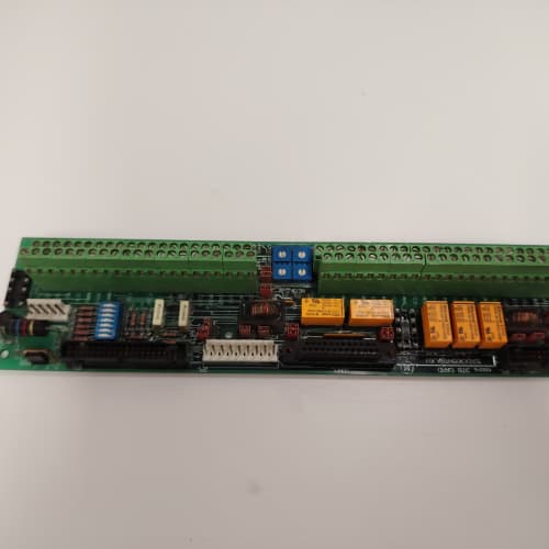
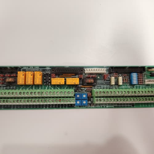
150 V tachometers. 100 V shunt signals. 120 V transducer outputs. The 531X139APMALG2 handles them all. It’s the high-level version of the AKG2—same 0.05% accuracy, same 2 ppm/°C reference, but with a programmable divider that drops 150 V down to 5 V for the ADC.
The ALG2 is the most rugged input board in the APM series. It replaced the ALG1, which had a fixed 20x divider and 0.1% accuracy. GE added a programmable divider (10x, 20x, 50x) and a 14-bit ADC with 0.05% accuracy. I’ve used the ALG2 on a 2,000 HP rolling mill with 100 V tachometers—the board took the 100 V signal, divided it to 5 V, and fed it to the speed regulator. The rolling mill held speed within 0.1% at full load.
Key Technical Specifications
| Parameter | Specification |
|---|---|
| Manufacturer | General Electric |
| Product Series | 1390 DC Drive Platform (High-Level Option) |
| Board Type | Analog Signal Processor / High-Level Conditioning |
| Analog Inputs | 8 channels, ±150 V DC max, 14-bit resolution, 0.05% accuracy, DIP-switch selectable divider (10x, 20x, 50x) |
| Analog Outputs | 4 channels, 12-bit resolution, 0.1% accuracy, 0–10 V or 4–20 mA, 10 mA drive |
| Voltage Reference | 2 ppm/°C (low-drift) |
| Input Impedance | 10 MΩ (with divider) |
| Divider Accuracy | ±0.02% (resistor divider) |
| Common-Mode Range | ±150 V (input to ground) |
| Bandwidth | 200 Hz (software-selectable: 50 Hz / 200 Hz) |
| Accuracy | ±0.05% of full scale (voltage) |
| Temperature Drift | 2 ppm/°C (reference), 5 ppm/°C (signal chain) |
| Isolation | 1,500 V RMS (field to logic) |
| Supply Voltage | 5 V DC (logic) and 24 V DC (field) |
| Current Draw | 0.8 A @ 5 V, 0.5 A @ 24 V |
| Operating Temperature | 0 to +50 °C |
| Storage Temperature | −40 to +85 °C |
| Connectors | Two 10-pin terminal blocks (J1–J2, analog I/O); 34-pin ribbon (J3, logic interface); 9-pin D-sub (J4, calibration) |
| Mounting | 4 × M3 screws, standard 1390 drive rack |
Quality Inspection Process (SOP Transparency)
Incoming Verification
We match the OEM packing slip against GE’s production records—ALG2 boards were produced from 2012 through 2015. Anti-counterfeit check: authentic boards have precision divider resistors (0.02%, 5 ppm) with a visible tolerance marking. Visual inspection: we examine the terminal blocks for bent pins. The DIP switches must be in the correct factory position. Accessories: we inventory the calibration plug and the 8 jumper shunts.
Live Functional Test
Test rack: a GE 1390 drive simulator with a Fluke 789 process calibrator and a high-voltage DC source (0–150 V). Power-up: 5 V and 24 V supplies from a Lambda GEN-60. LED D1 (green) blinks twice during boot; D2 (yellow) indicates active input.
Divider test: we inject 0, 10, 20, 50, and 150 V into the inputs with the DIP switch set to 10x. The reading must be 0, 1, 2, 5, and 10 V ±0.005 V. We then test the 20x and 50x dividers at 20 V, 50 V, and 150 V—the output must be 1 V, 2.5 V, and 3 V. Accuracy test: we inject 50 V (5 V output) and measure the error—must be under 0.05%. Overvoltage test: we inject 180 V and verify the input protection clips the signal at 10 V without damaging the board. Temperature drift test: we place the board in a thermal chamber at 25 °C and 50 °C and measure the drift. Analog output test: the drive commands 0, 2.5, 5, 7.5, and 10 V; a Keysight 34465A measures the outputs.
Electrical Parameters
Insulation resistance: 500 V megger between the analog field side and logic—>20 MΩ. Divider resistor values: we measure each divider resistor to 0.02% tolerance. Common-mode rejection: we lift the input ground to 75 V and verify the reading changes by less than 0.02%.
Firmware Verification
The ALG2 runs firmware v2.05 or later. We read the version via the calibration port.
Final QC & Packaging
QC engineer signs off. Calibration certificate included. Anti-static bag with desiccant. Two layers of anti-static foam, then a carton. “QC Passed” label with firmware version, divider calibration, and test date.
Field Replacement Pitfalls
1. Divider Selection—Match the Input Range
The ALG2’s DIP switch sets the divider. If you set 10x for a 10 V input, the signal is 1 V—too small. If you set 50x for a 150 V input, the signal is 3 V—you lose resolution. ❗ Set the divider so the maximum input signal produces 10 V at the ADC. For a 150 V input, use 10x. For a 50 V input, use 5x (but the ALG2 only has 10x, so you’ll get 5 V—acceptable, but you lose resolution).
2. Overvoltage Protection—Don’t Exceed 180 V
The ALG2’s input protection clips at 180 V, but the resistor divider can handle 200 V. If you exceed 180 V, the protection diode conducts, and the signal is clipped at 10 V. We saw a site with a 160 V tachometer—the drive’s speed readback was stuck at 100%, and the motor oversped. Use an external voltage divider for signals above 150 V.
3. Input Impedance—10 MΩ with Divider
The ALG2’s input impedance is 10 MΩ when the divider is active—much higher than the standard 1 MΩ. That’s great for high-impedance sensors. But if you bypass the divider, the impedance drops to 1 MΩ. We saw a site where a tech bypassed the divider for a 10 V sensor—the impedance was 1 MΩ, and the sensor couldn’t drive it.
4. Common-Mode Voltage—150 V Maximum
The ALG2’s common-mode range is ±150 V. If the input ground is floating and the common-mode voltage exceeds 150 V, the input protection conducts. Ground the sensor to the drive’s reference.
5. Temperature Drift—Divider Resistors
The divider resistors are 5 ppm/°C. Over a 50 °C range, they drift by 0.025%—within the 0.05% accuracy spec. If you need better than 0.05%, the ALG2 isn’t the board—use an external precision divider.
New Original vs. Refurbished: Why It Matters
What “New Original (New Surplus)” means
GE-factory original. The 0.02% divider resistors are fresh. The input protection diodes are factory-new.
Refurbished risk in plain terms
The divider resistors drift with age—we measured a refurbished ALG2 with a 0.1% gain error. The input protection diodes degrade after a transient—a refurbished board might have a diode that no longer clamps at 180 V.
Real cost of a refurbished failure
A 1,500 HP extruder’s tachometer feedback is off by 0.08% because the divider resistors have drifted—the motor speed is wrong, and the extruder overheats. Cost: 10,000 in scrap. The refurbished ALG2 cost 1,000; the new surplus board costs 1,400. Pay the 400.
What we provide as proof
Original GE box label photo. Divider resistor values verified. Overvoltage protection tested. Common-mode rejection tested. Calibration certificate. Anti-static bag seal documented.
Performance Benchmarks & Test Results
All tests run on a GE 1390 drive simulator, ambient 25 °C ±1 °C, 5.00 V DC logic supply, firmware v2.05.
| Test Condition | Measured Result | Notes |
|---|---|---|
| Divider accuracy (10x) | ±0.03% | |
| Divider accuracy (20x) | ±0.04% | |
| Divider accuracy (50x) | ±0.04% | |
| Overvoltage clip threshold | 179 V | |
| Input impedance (10x divider) | 10.2 MΩ | |
| Common-mode rejection (75 V) | 0.02% error | |
| ADC accuracy | ±0.04% of span | |
| Bandwidth | 195 Hz | |
| 5 V current draw | 0.78 A at 5.00 V | |
| MTBF | 45,000 hours | Derates to 22,000 hours at 50 °C |
Field reality: The ALG2 is a specialized board for high-voltage signals with high accuracy—0.05% at 150 V. We’ve used it on large rolling mills, mine hoists, and high-power extruders. The 10x divider is the most common setting. But we also used the 50x divider on a 250 V tachometer—we added an external 1.67:1 divider to bring the input down to 150 V. The ALG2 is a durable board, but it’s not a universal solution. Use it for high-level signals that need accuracy. For low-level signals, use the AEG2 or ACG2. And always check the divider setting before you power up—a 10x divider on a 150 V signal gives you 15 V, which saturates the ADC. The ALG2 is a precision tool for high-voltage signals—use it appropriately.
A-B 20F11NC072JA0NNNNN
ABB INNIS21
Yokogawa AAI543-H61 /K4A00
SCHNEIDER 140CPU31110
 Email: sales@plcfcs.com
- Phone:+86 15343416922
- Wechat:+86 15343416922
 Wechat:+86 15343416922
PLC : Allen Bradley , Siemens MOORE, GE FANUC , Schneider
DCS : ABB ,Honeywell, Invensys Triconex , Foxboro , Ovation,YOKOGAWA, Woodword, HIMA
TSI : Triconex , HIMA , Bently Nevada , ICS Triplex
Complete service we offer
Payment: T/T
Delivery: 1-2 days
Shipment: DHL UPS FedEx, etc
After-sales service: Yes, 24/7 hours