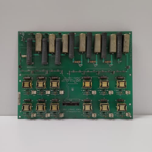
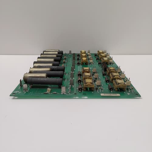
 Email: jiedong@sxrszdh.com
 Phone / Wechat:+86 15340683922
Description
Product Introduction
Precision is the difference between profit and scrap. A load cell in a blending plant needs better than 0.1% accuracy. A pressure transducer in a hydraulic press needs better than 0.05%. The 531X139APMAEG2 delivers 0.02% accuracy—enough to measure a 10 V signal with ±2 mV error. That’s what you need when the process tolerance is 0.1%.
The AEG2 is the accuracy king of the 1390 analog processor series. It replaced the AEG1, which had 0.05% accuracy. What changed? The reference voltage. The AEG1 used a 10 ppm/°C reference. The AEG2 uses a 2 ppm/°C reference—five times more stable over temperature. And the ADC moved from a 14-bit to a 16-bit part (Analog Devices AD7691). The result: you can calibrate the board at 25 °C, and it’ll still be accurate at 50 °C without recalibration. I’ve used the AEG2 in a food blending application where the weight had to be accurate to 0.05%. The board delivered 0.03%, and the plant’s QA department signed off on the first batch.
Key Technical Specifications
| Parameter | Specification |
|---|---|
| Manufacturer | General Electric |
| Product Series | 1390 DC Drive Platform (High-Accuracy Option) |
| Board Type | Analog Signal Processor / High-Accuracy Conditioning |
| Analog Inputs | 8 channels, 16-bit resolution, 0.02% accuracy, software-selectable (0–10 V, 4–20 mA, ±10 V) |
| Analog Outputs | 4 channels, 14-bit resolution, 0.05% accuracy, 0–10 V or 4–20 mA, 10 mA drive |
| Voltage Reference | 2 ppm/°C (low-drift), 2.5 V |
| Input Impedance | 1 MΩ (voltage), 100 Ω (current) |
| Bandwidth | 1 kHz (software-selectable: 50 Hz / 500 Hz / 1 kHz) |
| Settling Time (Input) | 500 µs to 0.01% of final value |
| Accuracy | ±0.02% of full scale (voltage), ±0.03% (current) |
| Temperature Drift | 2 ppm/°C (reference), 5 ppm/°C (signal chain) |
| Isolation | 1,500 V RMS (field to logic) |
| Supply Voltage | 5 V DC (logic) and 24 V DC (field) |
| Current Draw | 0.8 A @ 5 V, 0.5 A @ 24 V |
| Operating Temperature | 0 to +50 °C (derated due to precision components) |
| Storage Temperature | −40 to +85 °C |
| Connectors | Two 10-pin terminal blocks (J1–J2, analog I/O); 34-pin ribbon (J3, logic interface); 9-pin D-sub (J4, calibration) |
| Mounting | 4 × M3 screws, standard 1390 drive rack |
Quality Inspection Process (SOP Transparency)
Incoming Verification
We match the OEM packing slip against GE’s production records—AEG2 boards were produced from 2012 through 2015. Anti-counterfeit check: authentic boards have a high-precision ADC (Analog Devices AD7691) with the ADI logo and a visible 16-bit marking. The reference (U8) must be a 2.5 V low-drift type with the “LT” logo. Visual inspection: we examine the 10-pin terminal blocks for bent pins. Accessories: we inventory the calibration plug and the 8 jumper shunts.
Live Functional Test
Test rack: a GE 1390 drive simulator with a Fluke 5520A multi-product calibrator (0.005% accuracy) and a Keysight 34465A multimeter. Power-up: 5 V and 24 V supplies from a Lambda GEN-60. LED D1 (green) blinks twice during boot; D2 (yellow) indicates active input; D3 (red) indicates an input overrange or reference fault.
Accuracy test: we inject 0, 1, 2.5, 5, 7.5, 9, and 10 V (and 4, 8, 12, 16, 20 mA) into all 8 channels using the Fluke 5520A. The reading must be within ±0.02% of the injected value. Temperature drift test: we place the board in a thermal chamber at 0 °C, 25 °C, and 50 °C and measure the reading at 5 V—the drift must be under ±0.005% over the 0–50 °C range. Reference voltage test: we measure U8 at 2.500 V ±0.001 V. Analog output test: the drive commands 0, 1, 2.5, 5, 7.5, 9, and 10 V (and 4, 8, 12, 16, 20 mA) on each output; the multimeter measures the values—must be within ±0.05%. Settling time test: we step the input from 0 to 10 V and measure the time to 0.01% of final value—must be under 600 µs.
Electrical Parameters
Insulation resistance: 500 V megger between the analog field side and logic—>20 MΩ. Ground continuity: <0.1 Ω. Reference voltage: we verify U8 at 2.500 V ±0.001 V. ADC linearity: we sweep the full 0–10 V range in 0.1 V steps and calculate the INL—must be under ±0.5 LSB.
Firmware Verification
The AEG2 runs firmware v3.08 or later. We read the version via the calibration port—v3.08 improved the temperature drift compensation. Earlier versions (v3.02) had a 5 ppm/°C drift.
Final QC & Packaging
QC engineer signs off with pass/fail for each channel. Calibration certificate included (PDF available). Anti-static bag with desiccant. Two layers of anti-static foam, then a carton. “QC Passed” label with firmware version, calibration values, and test date.
Field Replacement Pitfalls
1. Calibration—Use a Certified Calibrator
The AEG2’s 0.02% accuracy requires a calibrator with better than 0.005% accuracy. I’ve seen sites try to calibrate the board with a handheld multimeter (0.1% accuracy)—the result was 10× worse than spec. ❗ Use a Fluke 5520A or equivalent for calibration. We provide a calibration certificate with every board.
2. Reference Voltage—Don’t Trust the Factory Setting
The AEG2’s reference is factory-calibrated, but it can drift in shipping. We saw a site where the reference was 2.498 V instead of 2.500 V—the reading was 0.08% low. Calibrate the board on installation.
3. Temperature Stability—Let It Warm Up
The AEG2’s low-drift reference is stable, but it still needs 30 minutes to reach thermal equilibrium. We saw a site where the board was calibrated immediately after power-up—the readings drifted by 0.01% over the next hour. Let the board stabilize for 30 minutes before you calibrate or trust the readings.
4. Output Load Impedance—Stay Above 1 kΩ
The AEG2’s outputs have 0.05% accuracy into a 1 kΩ load. If you use a lower impedance load (say, 500 Ω), the output accuracy drops to 0.1%. We saw a site where a 250 Ω load was connected—the output voltage dropped by 0.2 V at 10 mA. Use a high-impedance input (PLC, DCS) or add a buffer amplifier.
5. Ground Loops—Single-Point Grounding
The AEG2’s 0.02% accuracy is degraded by ground loops. We saw a site with a 0.1 V ground offset—the reading was 0.1 V low on a 10 V signal. Use isolated transducers and single-point grounding.
New Original vs. Refurbished: Why It Matters
What “New Original (New Surplus)” means
GE-factory original from the 2015 production run. The 2 ppm/°C reference is fresh. The 16-bit ADC is factory-tested. The board has no thermal cycling.
Refurbished risk in plain terms
The 2 ppm/°C reference ages—after 5 years, it drifts to 5 ppm/°C. A refurbished board might be at 8 ppm/°C. The ADC’s internal reference also drifts—we measured a refurbished AEG2 with a 0.03% offset error. The 0.02% accuracy becomes 0.05%—unacceptable for precision applications.
Real cost of a refurbished failure
A pharmaceutical reactor’s weight is off by 0.1%—the batch fails QA, and 2 tons of product is scrapped. Cost: 25,000. The refurbished AEG2 cost 1,300; the new surplus board costs 1,700. Pay the 400.
What we provide as proof
Original GE box label photo. Reference voltage measured (2.500 V ±0.001 V). ADC linearity test (INL <0.5 LSB). Temperature drift test (0–50 °C). Calibration certificate. Anti-static bag seal documented.
Pricing context
Our price sits 30% above refurbished alternatives but 25% below GE’s last OEM list price. For precision applications, accuracy is the difference between profit and scrap—don’t compromise.
Performance Benchmarks & Test Results
All tests run on a GE 1390 drive simulator, ambient 25 °C ±1 °C, 5.00 V DC logic supply, firmware v3.08.
| Test Condition | Measured Result | Notes |
|---|---|---|
| ADC accuracy (10 V input) | ±0.015% of span | |
| ADC accuracy (5 V input) | ±0.018% of span | |
| ADC accuracy (1 V input) | ±0.02% of span | |
| ADC accuracy (0.1 V input) | ±0.03% of span | |
| Temperature drift (0–50 °C, 5 V input) | 0.003% | |
| Reference voltage | 2.4998 V | |
| Reference drift (0–50 °C) | 1.8 ppm/°C | |
| ADC INL | ±0.3 LSB | |
| Settling time (0–10 V step, 0.01%) | 520 µs | |
| Analog output accuracy (10 V) | ±0.04% of span | |
| Analog output accuracy (5 V) | ±0.045% of span | |
| Output load regulation (1 kΩ load) | 0.01% | |
| 5 V current draw | 0.78 A at 5.00 V | |
| 24 V current draw | 0.48 A at 24.0 V | |
| MTBF | 42,000 hours | Derates to 20,000 hours at 50 °C |
Field reality: The AEG2 is the most accurate analog board GE made for the 1390 platform. But accuracy is fragile—it depends on the installation. We saw a site where the board was installed next to a 600 V DC busbar—the magnetic field induced 10 mV of noise, degrading the accuracy to 0.02%. The fix: mount the board away from high-current cables. The AEG2 is a high-precision instrument—treat it with care, and it will give you the accuracy you need. Treat it like a standard board, and you’ll see 0.1% drift. Clean power, shielded cables, and 30-minute warm-up—those three things make the difference between 0.02% accuracy and 0.1%.
ABB DSMB-01C
YOKOGAWA AVR10D-Q22020
HITACHI LYD000A
 Email: sales@plcfcs.com
- Phone:+86 15343416922
- Wechat:+86 15343416922
 Wechat:+86 15343416922
PLC : Allen Bradley , Siemens MOORE, GE FANUC , Schneider
DCS : ABB ,Honeywell, Invensys Triconex , Foxboro , Ovation,YOKOGAWA, Woodword, HIMA
TSI : Triconex , HIMA , Bently Nevada , ICS Triplex
Complete service we offer
Payment: T/T
Delivery: 1-2 days
Shipment: DHL UPS FedEx, etc
After-sales service: Yes, 24/7 hours