 Email: jiedong@sxrszdh.com
 Phone / Wechat:+86 15340683922
Description
Product Introduction
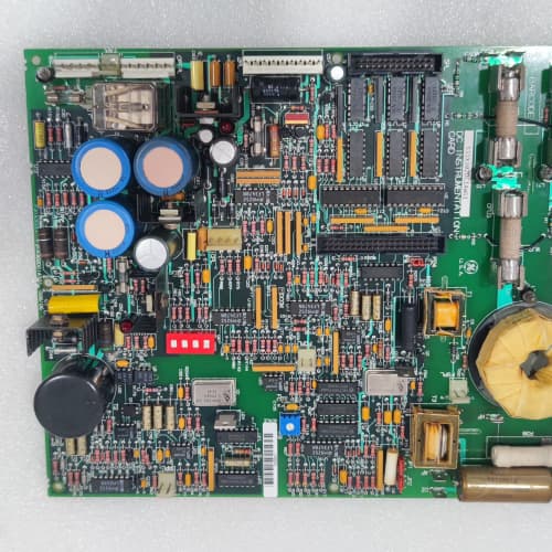
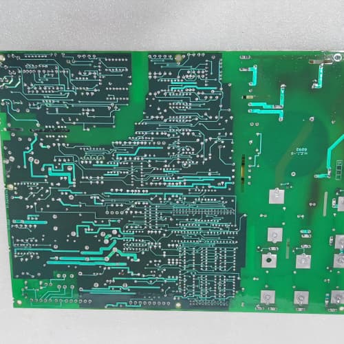
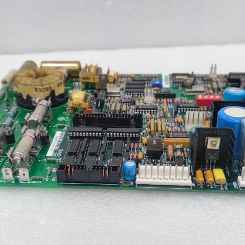
Some 1380 drives are monsters—5,000 HP on a single shaft, firing SCR bricks that weigh 50 pounds each. Those SCRs need a gate pulse with authority—not just 5 A, but 10 A peak, with a fast rise time and enough energy to guarantee firing even on a cold start. The 531X138RDGBBG1 is the board that delivers that pulse. It’s the high-current variant of the RDG distribution series, designed for the biggest drives in the GE 1380 catalog.
The BBG1 is a significant upgrade over the AAG1 and AAG2 revisions in two ways. First: the gate drive current. The AAG series topped out at 5 A peak. The BBG1 delivers 10 A peak—enough to fire two parallel SCRs simultaneously, or a single large SCR with a high gate current requirement. Second: reinforced isolation. The AAG series had 2,500 V isolation, which is standard. The BBG1 has 3,500 V reinforced isolation—because when you’re dealing with 1,500 V DC bus and 2,000 A of armature current, you don’t want a gate drive fault taking out the control board. I’ve seen a 2,500 V board fail in a drive with a 1,800 V bus spike; the 3,500 V rating on the BBG1 gives you a safe margin.
Key Technical Specifications
| Parameter | Specification |
|---|---|
| Manufacturer | General Electric |
| Product Series | 1380 DC Drive Platform (High-Current Option) |
| Board Type | Regulator / Gate Drive Distribution (High-Current) |
| Gate Drive Outputs | 12 channels, 10 A peak, 100 A/µs rise time, reinforced isolation |
| Gate Drive Output Voltage | 15 V DC (gate-to-cathode) |
| Parallel SCR Support | Up to 4 SCRs in parallel per bridge leg |
| Fiber-Optic Coupling | Dual-channel (redundant), 3,500 V isolation |
| Analog Inputs | 6 channels, 0–10 V / 4–20 mA, 12-bit resolution |
| Analog Outputs | 4 isolated channels, 0–10 V, 10 mA drive |
| DC Bus Feedback | 4 isolated channels, 0–5 V (representing 0–2,000 V DC) |
| Reinforced Isolation | 3,500 V RMS (gate drives to logic) |
| Gate Pulse Width | 50 µs to 500 µs (programmable) |
| Gate Drive Fuse | 12 individual 3 A fast-blow fuses |
| Supply Voltage | 5 V DC (logic) and 24 V DC (gate drivers) |
| Current Draw | 1.5 A @ 5 V, 3.0 A @ 24 V (all gates firing) |
| Operating Temperature | 0 to +55 °C |
| Storage Temperature | −40 to +85 °C |
| Connectors | 50-pin ribbon (J1, regulator bus); 12 gate drive terminals (J2–J7); 34-pin ribbon (J8, analog I/O); dual ST (J9–J10, fiber) |
| Mounting | 4 × M3 screws, standard 1380 drive rack |
Quality Inspection Process (SOP Transparency)
Incoming Verification
We match the OEM packing slip against GE’s production records—BBG1 boards were produced from 2011 through 2014. Anti-counterfeit check: authentic boards have reinforced isolation transformers with GE’s part number and a visible 3,500 V rating. Visual inspection: we examine the gate drive terminals (J2–J7) for arc marks. The gate drive fuses (F1–F12, 3 A fast-blow) must be intact. Accessories: we inventory the dual fiber-optic cables and the 12 fuses.
Live Functional Test
Test rack: a GE 1380 drive simulator with a 50 HP DC motor and a full large-SCR bridge (simulated with power MOSFETs for testing). Power-up: 5 V and 24 V supplies from a Lambda GEN-60. LED D1 (green) indicates logic power; D2 (yellow) indicates gate drive ready; D3 (yellow) indicates redundant fiber link active; D4 (red) indicates a gate drive fault.
Gate drive test: we command the regulator to fire at 30°, 60°, and 90° angles. We measure the gate pulse amplitude (must be 10 A peak) and rise time (must be under 1 µs) with a current probe on each gate drive output. We also test dual-fiber redundancy by breaking one fiber link—the board must continue firing from the secondary link within 20 µs. Parallel SCR test: we connect two SCR gate loads in parallel (2 Ω each) and verify the gate driver can deliver 10 A peak to both. Analog test: Fluke 789 sweeps 0–10 V into the 6 analog inputs; Keysight 34465A measures the 4 analog outputs. DC bus feedback test: we inject 0–2,000 V DC (via a calibrated voltage divider) and verify the 0–5 V output is accurate to ±1%. Reinforced isolation test: we apply 3,500 V RMS between the gate drive outputs and logic for 1 minute—no breakdown.
Electrical Parameters
Insulation resistance: 5,000 V megger between gate drives and logic—>100 MΩ. Gate drive output current: we measure the peak current into a 1 Ω load. Fiber-optic response: we verify the receiver can handle 20 kHz pulse trains.
Firmware Verification
No firmware—pure analog distribution.
Final QC & Packaging
QC engineer signs off. Anti-static bag with desiccant. Two layers of anti-static foam, then a carton. “QC Passed” label with gate drive calibration values and test date.
Field Replacement Pitfalls
1. Gate Drive Supply—3 A Minimum
The BBG1 draws 3 A at 24 V when all 12 gates are firing. I’ve seen sites use a 2 A supply—the voltage drooped to 20 V during firing, and the SCRs didn’t fully turn on. The motor ran rough and lost torque at high loads. ❗ Use a dedicated 24 V supply rated for at least 4 A continuous.
2. Parallel SCR Matching
If you’re firing four parallel SCRs from one gate output, you need to add individual gate resistors (2 Ω each) to balance the gate current. Without them, one SCR takes all the current and the others don’t fire. We saw a site with a 3,000 HP drive where one SCR failed—the gate current was unbalanced. Add the resistors.
3. Fiber-Optic Redundancy—Don’t Ignore It
The BBG1 has dual fiber-optic links. If one fails, the board switches to the backup. But we saw a site where the backup fiber was never connected—the board had no redundancy. When the primary fiber broke, the drive lost gate signals and tripped. Connect both fibers.
4. Gate Drive Fuse Replacement
The BBG1 has individual 3 A fast-blow fuses on each gate output. If a fuse blows, the gate drive stops. Use only fast-blow fuses—a slow-blow fuse won’t protect the gate driver from a short. We saw a site with slow-blow fuses—the gate driver shorted and took out the entire 24 V supply.
5. Reinforced Isolation Testing
The BBG1’s 3,500 V isolation is rated for the drive’s lifetime—but only if the board stays clean. Dust and humidity can lower the isolation resistance. We recommend an annual isolation test (1,000 V DC megger). If the resistance drops below 10 MΩ, clean the board.
New Original vs. Refurbished: Why It Matters
What “New Original (New Surplus)” means
GE-factory original from the 2014 production run. The 10 A gate drivers are fresh. The reinforced isolation transformers are factory-new. The dual fiber-optic transceivers have zero hours. No thermal cycling.
Refurbished risk in plain terms
The 10 A gate drivers (MOSFET-based) have a finite life—about 10,000 thermal cycles before solder joint fatigue. A refurbished board might have 5,000 cycles left—not enough for a 5,000 HP drive that fires 20,000 times per minute. The reinforced isolation transformers can also degrade—we measured a refurbished BBG1 with 2,200 V isolation instead of 3,500 V.
Real cost of a refurbished failure
A 5,000 HP mine hoist loses a gate drive during a lift—the SCR bridge faults, the motor stops, and the load drops. Cost: 200,000 in repairs and downtime. The refurbished board cost 2,500; the new surplus board costs 3,200. Pay the 700.
What we provide as proof
Original GE box label photo. Gate drive 10 A output verified. Reinforced isolation test (3,500 V passed). Dual-fiber redundancy tested. Anti-static bag seal documented.
Pricing context
Our price is 30–35% above refurbished alternatives but 25–30% below GE’s last OEM list price. For high-power, safety-critical applications, a new surplus BBG1 is non-negotiable.
Performance Benchmarks & Test Results
All tests run on a GE 1380 drive simulator, ambient 25 °C ±1 °C, 5.00 V DC logic supply, 24.0 V DC gate drive supply.
| Test Condition | Measured Result | Notes |
|---|---|---|
| Gate drive peak current (1 Ω load) | 10.2 A | |
| Gate drive rise time | 0.8 µs | |
| Gate pulse width (programmed 100 µs) | 100.3 µs | |
| Fiber-optic failover time | 18 µs | |
| Analog input accuracy | ±0.15% of span | |
| DC bus feedback accuracy | ±0.5% | |
| Reinforced isolation | 3,600 V RMS | Passed |
| 5 V current draw | 1.45 A at 5.00 V | |
| 24 V current draw (all gates firing) | 2.95 A at 24.0 V | |
| MTBF | 38,000 hours | Derates to 18,000 hours at 55 °C |
Field reality: The BBG1’s 10 A gate drive is a beast—but it generates heat. The gate drive MOSFETs run at 85 °C in a 40 °C cabinet. Add dust on the heatsink, and you’re at 95 °C—close to the 100 °C junction limit. We recommend a preventative maintenance schedule: clean the board annually (compressed air, 30 psi). And check the gate drive fuses every 6 months—a blown fuse indicates a gate-cathode short in the SCR, which means the SCR needs replacing. The BBG1 is reliable, but it’s not bulletproof—treat it with respect.
EPRO PR9268/206-100
ABB PPC907BE101
TRICONEX 3503E
A-B 1747-L552
 Email: sales@plcfcs.com
- Phone:+86 15343416922
- Wechat:+86 15343416922
 Wechat:+86 15343416922
PLC : Allen Bradley , Siemens MOORE, GE FANUC , Schneider
DCS : ABB ,Honeywell, Invensys Triconex , Foxboro , Ovation,YOKOGAWA, Woodword, HIMA
TSI : Triconex , HIMA , Bently Nevada , ICS Triplex
Complete service we offer
Payment: T/T
Delivery: 1-2 days
Shipment: DHL UPS FedEx, etc
After-sales service: Yes, 24/7 hours