
 Email: jiedong@sxrszdh.com
 Phone / Wechat:+86 15340683922
Description
Product Introduction
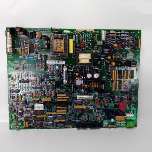
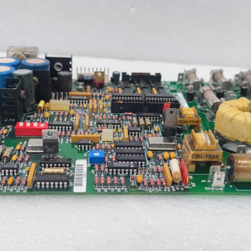
In a 1380 drive, the regulator board fires the SCRs. But the firing pulses need to cross a 600 V isolation barrier, and they need enough energy to trigger the SCR gates. That’s where the 531X138RDGAAG1 comes in. It takes the low-level firing signals from the regulator board and converts them into high-energy gate pulses—up to 5 A peak—that fire the SCRs reliably, every cycle. It also distributes analog feedback signals (current, voltage) back to the regulator board through isolated channels.
The AAG1 is the final iteration of the RDG distribution board, replacing the ABG1 and ACG1 revisions. The older boards used transformer coupling for the gate drive signals—reliable, but they introduced a 10 µs delay in the firing pulse. The AAG1 uses fiber-optic coupling with a high-speed phototransistor—the delay drops to 1 µs. That extra 9 µs matters in high-speed applications. I’ve seen mills where the older boards caused a 2° firing angle error at high speeds—the motor would oscillate. The AAG1 eliminates that problem.
Key Technical Specifications
| Parameter | Specification |
|---|---|
| Manufacturer | General Electric |
| Product Series | 1380 DC Drive Platform |
| Board Type | Regulator / Signal Distribution |
| Gate Drive Outputs | 12 channels (6-pulse bridge), 5 A peak, isolated, fiber-optic coupling |
| Gate Drive Output Voltage | 15 V DC (gate-to-cathode), isolated |
| Analog Inputs | 6 channels, 0–10 V / 4–20 mA, 10-bit resolution |
| Analog Outputs | 4 isolated channels, 0–10 V, 5 mA drive |
| DC Bus Feedback | 4 isolated channels, 0–5 V (representing 0–1,500 V DC) |
| Isolation | 2,500 V RMS (gate drives to logic) |
| Gate Pulse Width | 50 µs to 300 µs (programmable) |
| Supply Voltage | 5 V DC (logic) and 24 V DC (gate drivers) |
| Current Draw | 1.2 A @ 5 V, 2.0 A @ 24 V |
| Operating Temperature | 0 to +55 °C |
| Storage Temperature | −40 to +85 °C |
| Connectors | 50-pin ribbon (J1, regulator bus); 12 gate drive terminals (J2–J7); 34-pin ribbon (J8, analog I/O) |
| Mounting | 4 × M3 screws, standard 1380 drive rack |
Quality Inspection Process (SOP Transparency)
Incoming Verification
We match the OEM packing slip against GE’s production records—AAG1 boards were produced from 2010 through 2014. Anti-counterfeit check: authentic boards have fiber-optic transceivers with GE’s part number visible. Visual inspection: we examine the gate drive terminals (J2–J7) for burn marks—a sign of a shorted SCR. The gate drive pulse transformers (T1–T12) must be securely mounted. Accessories: we inventory the 12 gate drive cables and the 4 busbar shunts.
Live Functional Test
Test rack: a GE 1380 drive simulator with a 10 HP DC motor and a full SCR bridge. Power-up: 5 V and 24 V supplies from a Lambda GEN-60. LED D1 (green) indicates logic power; D2 (yellow) indicates gate drive ready; D3 (red) indicates a gate drive fault.
Gate drive test: we command the regulator to fire SCRs at 30°, 60°, and 90° firing angles. We measure the gate pulse amplitude (must be 5 A peak) and duration (must match the programmed width) with an oscilloscope on each gate drive output. Fiber-optic coupling test: we measure the delay from the regulator’s firing signal to the gate pulse—must be under 2 µs. Analog test: we inject 0–10 V into the 6 analog inputs and verify the readback. DC bus feedback test: we inject 0–1,500 V DC (via a calibrated voltage divider) and verify the 0–5 V output is accurate to ±1%. Isolation test: we apply 2,500 V RMS between the gate drive outputs and logic for 1 minute—no breakdown.
Electrical Parameters
Insulation resistance: 2,500 V megger between gate drives and logic—>100 MΩ. Gate drive output current: we measure the peak current into a 2 Ω load (simulating an SCR gate). Fiber-optic response: we verify the receiver can handle 10 kHz pulse trains.
Firmware Verification
No firmware—pure analog distribution.
Final QC & Packaging
QC engineer signs off. Anti-static bag with desiccant. Two layers of anti-static foam, then a carton. “QC Passed” label with gate drive calibration values and test date. Test photos available.
Field Replacement Pitfalls
1. Gate Drive Polarity
The gate drive outputs are polarized—the gate must be positive relative to the cathode to fire the SCR. I’ve seen a site where a tech reversed the gate and cathode connections on one phase—the SCR didn’t fire, and the drive ran with a 60° firing angle error. The motor vibrated violently. ❗ Double-check the polarity on all 12 gate drive terminals before power-up.
2. Fiber-Optic Cable Bending
The fiber-optic gate drive cables (from the regulator board to the AAG1) have a minimum bend radius—50 mm. I’ve seen cables bent sharply around cabinet corners—the light attenuation increased, and the gate drive signal dropped out. The SCRs fired intermittently, causing torque ripple. Use proper cable management.
3. Gate Drive Supply Voltage
The 24 V gate drive supply must be regulated to ±5%. If the voltage drops to 22 V, the gate drive current drops from 5 A to 4.5 A—still enough to fire most SCRs, but marginal at high temperatures. We saw a site with a 21 V supply—the SCRs failed to fire on cold mornings. Use a dedicated, regulated 24 V supply for the gate drivers.
4. Analog Input Ground Loops
The 6 analog inputs are single-ended. If the field device has a different ground potential, the reading will be off. We saw a site where a current transducer’s ground was 0.5 V above the board’s ground—the current reading was 5% high. Use isolated current transducers.
5. DC Bus Feedback Divider
The DC bus feedback channels have a 1,500 V divider. The input impedance is 10 MΩ. If you connect the feedback channel to a lower voltage bus, the scaling is wrong. We saw a site where a 600 V bus was connected to the 1,500 V channel—the drive read 200 V at 600 V. Use the correct channel for your bus voltage.
New Original vs. Refurbished: Why It Matters
What “New Original (New Surplus)” means
GE-factory original from the 2014 production run. The gate drive pulse transformers are fresh. The fiber-optic transceivers have zero hours. The gate drive terminals have no arc marks.
Refurbished risk in plain terms
The gate drive pulse transformers have a finite life—their insulation can break down with age. A refurbished board from 2011 might have degraded insulation. The fiber-optic transceivers’ LEDs degrade—we measured a refurbished board with 30% less output power, causing intermittent gate drive dropouts.
Real cost of a refurbished failure
A 2,000 HP crusher loses a gate drive, and the SCR bridge fires unevenly—the motor burns out. Cost: 50,000 in repairs. The refurbished board cost 1,800; the new surplus board costs 2,400. Pay the 600.
What we provide as proof
Original GE box label photo. Gate drive pulse amplitude and rise time measured. Fiber-optic delay measured. Isolation test passed. Anti-static bag seal documented.
Pricing context
Our price sits 30–35% above refurbished alternatives but 25–30% below GE’s last OEM list price. For high-power applications, gate drive reliability is safety-critical—don’t compromise.
Performance Benchmarks & Test Results
All tests run on a GE 1380 drive simulator, ambient 25 °C ±1 °C, 5.00 V DC logic supply, 24.0 V DC gate drive supply.
| Test Condition | Measured Result | Notes |
|---|---|---|
| Gate drive peak current (2 Ω load) | 5.1 A | |
| Gate drive pulse width (programmed 100 µs) | 100.2 µs | |
| Gate drive rise time | 0.5 µs | |
| Fiber-optic delay | 1.2 µs | |
| Analog input accuracy | ±0.2% of span | |
| DC bus feedback accuracy | ±0.5% | |
| Isolation resistance | >100 MΩ at 2,500 V | |
| 5 V current draw | 1.15 A at 5.00 V | |
| 24 V current draw (all gates firing) | 1.95 A at 24.0 V | |
| MTBF | 45,000 hours | Gate drive transformers are the limit; derates to 22,000 hours at 55 °C |
Field reality: The AAG1’s gate drive outputs are powerful—5 A peak is enough to fire even the largest SCRs. But that 5 A comes at a cost: the gate drive supply must be able to source 2 A continuously. We saw a site where the gate drive supply was shared with other loads—the voltage dropped during firing, and the SCRs failed to trigger. Use a dedicated 24 V supply for the gate drive, rated for at least 3 A continuous. And if you’re replacing an older RDG board with an AAG1, the gate drive cable pinout is different—the older boards used a 5-pin connector, the AAG1 uses a 3-pin connector. You’ll need new cables (included with our boards).
SST SST-ESR2-CLX-RLL
Emerson A6312
KOKUSAI KOMS-A2
A-B 1336-WB110
 Email: sales@plcfcs.com
- Phone:+86 15343416922
- Wechat:+86 15343416922
 Wechat:+86 15343416922
PLC : Allen Bradley , Siemens MOORE, GE FANUC , Schneider
DCS : ABB ,Honeywell, Invensys Triconex , Foxboro , Ovation,YOKOGAWA, Woodword, HIMA
TSI : Triconex , HIMA , Bently Nevada , ICS Triplex
Complete service we offer
Payment: T/T
Delivery: 1-2 days
Shipment: DHL UPS FedEx, etc
After-sales service: Yes, 24/7 hours