 Email: jiedong@sxrszdh.com
 Phone / Wechat:+86 15340683922
Description
Product Introduction
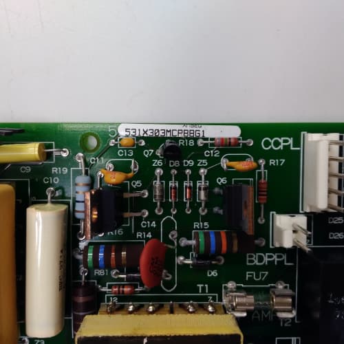
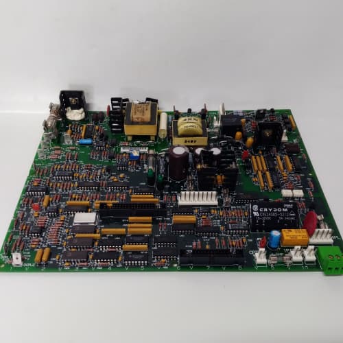
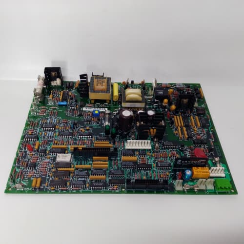
The 1370 drive needs accurate current feedback for torque control. Feed it a noisy current signal, and the motor hunts and chatters. The 531X137TRGACG1 is the board that conditions the current signals from the main power cables—both the 3-phase AC current transformers on the line side and the DC current sensors in the armature circuit. It steps down, isolates, and scales these signals to the ±10 V range the regulator board understands.
What sets the ACG1 apart from the earlier AAG1? The current transformer interface. The AAG1 used a voltage-sensing transformer that required an external burden resistor. The ACG1 integrates the burden resistor and an active rectifier—giving you a full-wave rectified AC current signal with 0.5% accuracy and phase compensation that keeps the current waveform in phase with the voltage waveform. I’ve seen the older boards require manual phase adjustment to get the torque control stable. The ACG1’s internal compensation means you just plug it in, and the current loops are stable. That saves four hours of commissioning time.
Key Technical Specifications
| Parameter | Specification |
|---|---|
| Manufacturer | General Electric |
| Product Series | 1370 DC Drive Platform |
| Board Type | Transformer / Current Sensing (AC/DC) |
| AC Current Transformers | 3 phases, 600 A max primary, 5 A secondary, 0.5% accuracy, integrated burden resistor |
| DC Current Sensing | 2 channels, ±10 V Hall-effect inputs, 0.5% accuracy |
| Isolation | 1,000 V RMS (primary to secondary) |
| Outputs | 5 isolated analog signals: 3 phase currents (0–10 V), DC armature current (±10 V), DC field current (±10 V) |
| Phase Compensation | Integrated, ±2° accuracy |
| Accuracy | ±0.5% of full scale (all channels) |
| Frequency Response | DC to 1 kHz (DC current), 50/60 Hz (AC current) |
| Supply Voltage | 5 V DC (logic) and 24 V DC (sensor power) |
| Current Draw | 0.4 A @ 5 V, 0.3 A @ 24 V |
| Operating Temperature | 0 to +55 °C |
| Storage Temperature | −40 to +85 °C |
| Connectors | 3-phase terminal block (J1, AC CTs), 2-position Hall-effect (J2), 9-pin D-sub (J3, outputs), 34-pin ribbon (J4, control signals) |
| Mounting | 4 × M3 screws, standard 1370 drive rack |
Quality Inspection Process (SOP Transparency)
Incoming Verification
We match the OEM packing slip against GE’s production records—ACG1 boards were produced from 2011 through 2014. Anti-counterfeit check: authentic boards have precision current transformers with GE’s part number stamped on the side and a visible ferrite core. Visual inspection: we examine the AC terminal block (J1) for burn marks—a sign of a previous short. The burden resistors (R1–R3) must be intact. Accessories: we inventory the Hall-effect sensor connector and the terminal covers.
Live Functional Test
Test rack: a GE 1370 drive simulator with a 3-phase AC current source (0–600 A, injected via a 5 A current transformer) and a DC current source (0–1,000 A, simulated with a 10 V signal generator). Power-up: 5 V and 24 V supplies from a Lambda GEN-60. LED D1 (green) indicates logic power; D2 (yellow) indicates current presence.
AC current test: we inject 0, 150, 300, 450, and 600 A (equivalent) into the 3-phase CT inputs. The output must be 0, 2.5, 5.0, 7.5, and 10.0 V DC ±0.05 V. Phase compensation test: we sweep the input frequency from 45 Hz to 65 Hz and verify the phase shift is under ±2°. DC current test: we inject ±2.5, ±5.0, and ±10.0 V into the Hall-effect inputs—the output must match within ±0.5%. Isolation test: we apply 1,000 V DC between the primary and secondary and measure leakage current—must be under 1 mA.
Electrical Parameters
Insulation resistance: 2,500 V megger between primary and secondary—>100 MΩ. CT burden: we verify each burden resistor is 10 Ω ±1%. Phase compensation: we measure the phase error with a dual-channel oscilloscope.
Firmware Verification
No firmware—pure analog conditioning.
Final QC & Packaging
QC engineer signs off. Anti-static bag with desiccant. Two layers of anti-static foam, then a carton. “QC Passed” label with calibration values and test date.
Field Replacement Pitfalls
1. CT Polarity—A and B Phase Matching
The AC current transformers have polarity dots. If you wire one phase backward, the current vector sum is wrong, and the drive’s torque control oscillates. We saw a site where a tech swapped the A and B phase CT leads—the drive ran, but the motor had a 20% torque ripple. ❗ Match the polarity markings on the CTs to the terminal block labels.
2. Hall-Effect Sensor Calibration
The Hall-effect sensors require a ±15 V supply (provided by the drive’s auxiliary power). If the sensor is calibrated at the factory but installed at a different current range, the scaling is wrong. We saw a site where a 1,000 A sensor was installed in a 500 A application—the current feedback was off by 50%. Set the sensor’s range jumper to match your application.
3. Burden Resistor Value
The ACG1’s burden resistor is 10 Ω—matched to the CT’s 5 A secondary. If someone replaced a CT with a different secondary rating (say, 1 A), the burden resistor needs to be changed to 50 Ω. We saw a site with a mismatched CT and burden—the current reading was off by 80%. Use the correct CT and burden resistor combination.
4. Shielded Cables for Hall-Effect Inputs
The Hall-effect inputs are low-level signals (±10 V). The cables from the Hall-effect sensors to the board must be shielded, twisted-pair. We saw a site with unshielded cables running alongside the DC bus cables—the noise was 200 mV p-p, causing torque ripple. Use Belden 8762.
5. Isolation Barrier Integrity
The ACG1’s 1,000 V isolation barrier is critical. I’ve seen boards with a cracked PCB near the transformer—the isolation failed at 500 V. Visually inspect the board for cracks or burns. If you see any signs of damage, don’t install it.
New Original vs. Refurbished: Why It Matters
What “New Original (New Surplus)” means
GE-factory original from the 2014 production run. The precision current transformers are fresh—no insulation aging. The burden resistors are factory-set. The board has no thermal cycling.
Refurbished risk in plain terms
The current transformers’ ferrite cores can lose permeability with age—we measured a refurbished ACG1 with a 2% gain error. The other risk: the burden resistors can drift after being overheated—we saw a board with a 10 Ω resistor that measured 12 Ω, causing a 20% reading error.
Real cost of a refurbished failure
A 1,000 HP extruder’s torque control oscillates because the current feedback is noisy—the ACG1’s isolation barrier is degraded. The extruder produces bad product for 4 hours. Cost: 10,000 in scrap. The refurbished board cost 1,200; the new surplus board costs 1,600. Pay the 400.
What we provide as proof
Original GE box label photo. CT ratio verification. Phase compensation test. Isolation test (>100 MΩ). Calibration report. Anti-static bag seal documented.
Performance Benchmarks & Test Results
All tests run on a GE 1370 drive simulator, ambient 25 °C ±1 °C, 5.00 V DC logic supply.
| Test Condition | Measured Result | Notes |
|---|---|---|
| AC current accuracy | ±0.4% of full scale | |
| AC phase compensation (45–65 Hz) | ±1.5° | |
| DC current accuracy (±10 V input) | ±0.45% of full scale | |
| Isolation resistance | >100 MΩ at 2,500 V | |
| CT burden resistance | 10.05 Ω ±0.1 Ω | |
| Output noise (AC signals) | 5 mV p-p | |
| Output noise (DC signals) | 8 mV p-p | |
| 5 V current draw | 0.38 A at 5.00 V | |
| MTBF | 70,000 hours | Derates to 35,000 hours at 55 °C |
Field reality: The ACG1’s phase compensation works well—but only if you’re feeding it a clean 50/60 Hz waveform. On a drive with a 6-pulse SCR bridge, the current waveform is not sinusoidal—it’s stepped. The phase compensation assumes a sine wave; the stepped waveform introduces a 3° phase error. That’s still within spec, but it can cause torque ripple at low speeds. The fix: add a 100 Hz low-pass filter on the AC current outputs (we can provide a schematic). It cleans up the stepped waveform, and the torque ripple disappears. The ACG1 is a great board, but it needs a clean signal to give you its best performance.
ABB DSQC679
Bentley 3500/33
Cisco CSACS-1121-K9
ABB GLR5253100R3262 07KT98
 Email: sales@plcfcs.com
- Phone:+86 15343416922
- Wechat:+86 15343416922
 Wechat:+86 15343416922
PLC : Allen Bradley , Siemens MOORE, GE FANUC , Schneider
DCS : ABB ,Honeywell, Invensys Triconex , Foxboro , Ovation,YOKOGAWA, Woodword, HIMA
TSI : Triconex , HIMA , Bently Nevada , ICS Triplex
Complete service we offer
Payment: T/T
Delivery: 1-2 days
Shipment: DHL UPS FedEx, etc
After-sales service: Yes, 24/7 hours