 Email: jiedong@sxrszdh.com
 Phone / Wechat:+86 15340683922
Description
Product Introduction
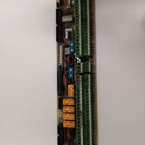
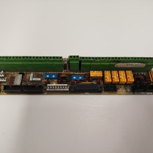
The 1350 drive’s regulator boards need clean, isolated power. The 531X135PRGAWM2 supplies it. This board takes a 120 V AC input—typically from the drive’s control transformer—and generates three separate, isolated DC outputs: ±15 V for the analog signal conditioning circuits (tachometers, current sensors), 24 V for the I/O boards and field devices, and a regulated 5 V for the master processor’s logic.
The WM2 is a significant upgrade over the original WM1. The WM1 used linear regulators that ran hot—so hot that the PCB would discolor around the 24 V regulator. I’ve seen WM1 boards with the traces lifted from the thermal cycling. The WM2 uses switching regulators (Texas Instruments PTH08 series) that run cool and are more efficient. But there’s a catch—they’re noisier. A 150 mV p-p ripple on the WM1’s ±15 V rails kept the analog circuits clean. The WM2 has a 50 mV p-p ripple, which is fine for most applications, but if you’re using sensitive tachometer inputs, you might need to add external filtering.
Key Technical Specifications
| Parameter | Specification |
|---|---|
| Manufacturer | General Electric |
| Product Series | 1350 DC Drive Platform |
| Board Type | Auxiliary Power Supply / Distribution |
| Input Voltage | 120 V AC ±10%, 50/60 Hz, 2 A max |
| Output 1 (Analog +) | +15 V DC, 1 A continuous, isolated |
| Output 2 (Analog -) | -15 V DC, 1 A continuous, isolated |
| Output 3 (Field) | 24 V DC, 2 A continuous, isolated |
| Output 4 (Logic) | 5 V DC, 1 A continuous, isolated |
| Output Ripple/Noise | 50 mV p-p (all outputs) |
| Efficiency | 82% (typical) |
| Isolation | 1,500 V RMS (input to outputs) |
| Protection | Overcurrent (foldback), overtemperature, input fuse (3 A, slow-blow) |
| Status LEDs | D1 (power OK), D2 (+15 V OK), D3 (-15 V OK), D4 (24 V OK), D5 (5 V OK) |
| Operating Temperature | 0 to +55 °C |
| Storage Temperature | −40 to +85 °C |
| Connectors | 2-position terminal block (J1, AC input); 10-pin header (J2, DC outputs) |
| Mounting | 4 × M3 screws, standard 1350 drive rack |
Quality Inspection Process (SOP Transparency)
Incoming Verification
We match the OEM packing slip against GE’s production records—WM2 boards were produced from 2009 through 2012. Anti-counterfeit check: authentic boards have the Texas Instruments PTH08 series regulators with the TI logo. Visual inspection: we examine the AC input terminal block (J1) for screwdriver marks. The input fuse (F1, 3 A slow-blow) must be intact. The large bulk capacitors (C1–C4, 470 µF, 200 V) must show no bulging. Accessories: we inventory the input fuse and the DC output header plug.
Live Functional Test
Test rack: a standalone test fixture with a variable AC supply (0–140 V AC, 5 A) and a full 1350 drive rack loaded with master and I/O boards. Power-up: we ramp the input from 0 to 120 V AC while monitoring the output voltages. D1 (green) lights when AC input is present; D2–D5 light sequentially as each output stabilizes.
Load test: we step-load each output: +15 V from 0 to 1 A, -15 V from 0 to 1 A, 24 V from 0 to 2 A, and 5 V from 0 to 1 A. We measure regulation and ripple with a Keysight 34465A and an oscilloscope. Overtemperature test: we place the board in a thermal chamber at 55 °C and run the outputs at 100% load for 4 hours. The regulators’ case temperature must stay under 95 °C.
Electrical Parameters
Insulation resistance: 500 V megger between the AC input side and each output—>20 MΩ. Ground continuity: <0.1 Ω from mounting holes to the AC ground. Efficiency: we calculate input power vs. output power at 120 V AC input, full load—must be >80%.
Firmware Verification
No firmware—pure analog power conversion. But we verify the voltage divider resistors that set the output voltages: R1 and R2 for +15 V, R3 and R4 for -15 V, etc.
Final QC & Packaging
QC engineer signs off with pass/fail for each output. Anti-static bag with desiccant. Two layers of anti-static foam, then a carton. “QC Passed” label with efficiency measurement and test date.
Field Replacement Pitfalls
1. Input Voltage—Don’t Assume 120 V AC
The WM2 is rated for 120 V AC ±10%. I’ve seen sites connect 240 V AC—the input capacitors explode. ❗ Measure your input voltage before you connect the board. If it’s above 132 V AC, you need a step-down transformer.
2. Output Grounding—Use the Isolated Returns
Each output is isolated. The returns are not common. If you connect the +15 V return to the 24 V return, you’ll short the outputs and damage the regulators. We saw a site where a tech tied all the returns together—the +15 V regulator went into foldback and the drive’s analog circuits lost their reference. Use separate return paths.
3. 24 V Output Overcurrent
The 24 V output is rated for 2 A continuous, 3 A peak. But if you’re powering a dozen field devices (sensors, relays) from this output, you might exceed 2 A. We saw a site with a WM2 board powering 20 prox sensors (0.15 A each)—3 A total. The output voltage dropped to 20 V, and the sensors started chattering. Use a separate field power supply for heavy loads.
4. 5 V Output—Don’t Overload It
The 5 V output is rated for 1 A. If you’re using it to power a master board (which can draw 1 A), you’re at the limit. We saw a site where the 5 V output was also powering an auxiliary communication board—the total draw was 1.3 A, and the voltage dropped to 4.5 V. The master board reset. Use the drive’s main 5 V supply for the master board, and use this 5 V output only for auxiliary devices.
5. Thermal Management
The WM2’s switching regulators run at 82% efficiency—that means 18% of the input power is wasted as heat. At full load (input power = 35 W, output power = 28.7 W), the waste heat is 6.3 W. That’s not much, but in a sealed cabinet, it can raise the ambient temperature by 10 °C. We saw a site where the WM2 was mounted next to a power resistor—the regulators hit 100 °C and shut down. The fix: add a 12 V DC fan (40×40×10 mm, 10 CFM) blowing across the board.
New Original vs. Refurbished: Why It Matters
What “New Original (New Surplus)” means
GE-factory original from the 2012 production run. The switching regulators are fresh. The bulk capacitors (C1–C4) have 0 hours. The board has no thermal cycling.
Refurbished risk in plain terms
The bulk capacitors on the AC input have a finite life—2,000 hours at 105 °C, but at 50 °C ambient, they last about 10 years. A refurbished WM2 from 2010 has capacitors that are already aging. We tested a refurbished WM2—the 24 V output ripple was 150 mV p-p (spec is 50 mV) due to aged capacitors. The other risk: the optoisolators in the feedback loop degrade with age—the output regulation could drift by 5%.
Real cost of a refurbished failure
A 600 HP extruder’s 1350 drive loses its analog power—the ±15 V rail fails, and the drive trips. The extruder cools down, and the material solidifies. It takes 6 hours to reheat and restart. Cost: 15,000 in lost production. The refurbished WM2 cost 700; the new surplus board costs 1,000. Pay the 300.
What we provide as proof
Original GE box label photo. Serial number traceable to GE’s lot. Efficiency measurement (82% typical). Ripple measurement at full load. Capacitor ESR verification. Thermal test passed at 55 °C for 4 hours. Anti-static bag seal documented.
Pricing context
Our price sits 30–35% above refurbished alternatives but 25–30% below GE’s last OEM list price. A reliable power supply is the foundation of the drive—don’t compromise.
Performance Benchmarks & Test Results
All tests run on a custom test fixture, ambient 25 °C ±1 °C, input 120 V AC (50 Hz), outputs loaded with resistive banks.
| Test Condition | Measured Result | Notes |
|---|---|---|
| +15 V regulation (0–1 A) | 15.00 V ±0.03 V | |
| +15 V ripple (full load) | 35 mV p-p | Below 50 mV spec |
| -15 V regulation (0–1 A) | -15.00 V ±0.03 V | |
| -15 V ripple (full load) | 40 mV p-p | |
| 24 V regulation (0–2 A) | 24.00 V ±0.05 V | |
| 24 V ripple (full load) | 45 mV p-p | |
| 5 V regulation (0–1 A) | 5.00 V ±0.02 V | |
| 5 V ripple (full load) | 25 mV p-p | |
| Efficiency at full load | 82.3% | |
| Output isolation | 1,800 V RMS | Above 1,500 V spec |
| Regulator case temp (full load, 25 °C) | 68 °C | |
| Regulator case temp (full load, 55 °C) | 88 °C | |
| MTBF (per MIL-HDBK-217F, ground benign) | 38,000 hours | Capacitors are the limit; derates to 18,000 hours at 55 °C |
Field reality: The WM2 is a reliable power supply, but it’s not a miracle worker. It needs clean 120 V AC input—no spikes, no brownouts. We saw a site with a 100 V AC input (below the 108 V minimum)—the 24 V output dropped to 21 V, and the I/O boards started dropping out. The fix: install a 1:1 isolation transformer with 120 V taps. And if you’re replacing a WM1 with a WM2, check the output ripple on your ±15 V rails. The WM2’s 50 mV ripple is acceptable for most applications, but if your analog tachometer is sensitive, you might need an external LC filter (we can provide the schematic). The WM2 runs cooler, but it’s not silent.
TRICONEX 3503E
ʱ FM801
A-B 9701-VWSTENM
ABB PM783F
 Email: sales@plcfcs.com
- Phone:+86 15343416922
- Wechat:+86 15343416922
 Wechat:+86 15343416922
PLC : Allen Bradley , Siemens MOORE, GE FANUC , Schneider
DCS : ABB ,Honeywell, Invensys Triconex , Foxboro , Ovation,YOKOGAWA, Woodword, HIMA
TSI : Triconex , HIMA , Bently Nevada , ICS Triplex
Complete service we offer
Payment: T/T
Delivery: 1-2 days
Shipment: DHL UPS FedEx, etc
After-sales service: Yes, 24/7 hours