 Email: jiedong@sxrszdh.com
 Phone / Wechat:+86 15340683922
Description
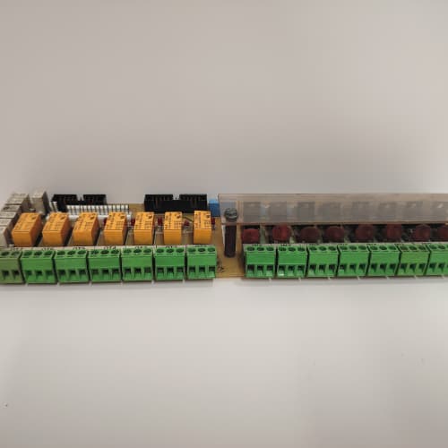
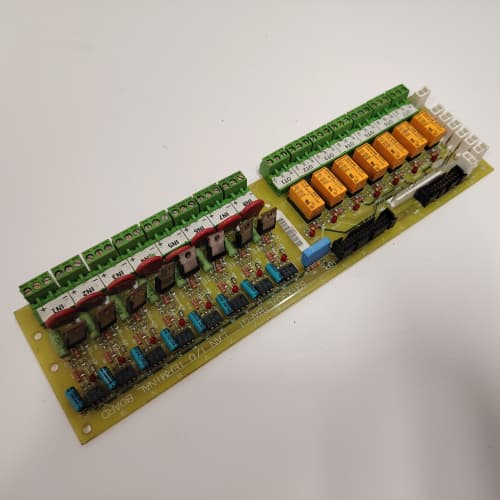
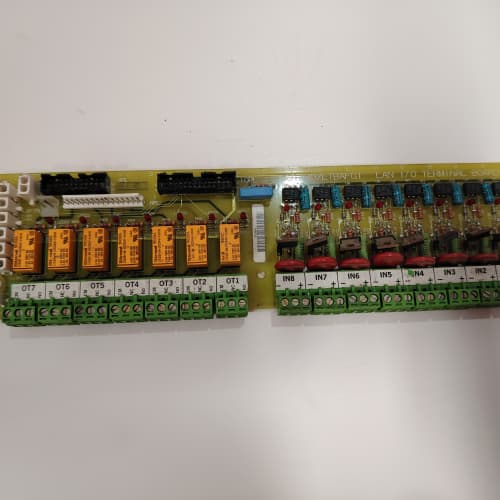
Product Introduction
Fuel valves don’t move themselves—they need a command signal. The 531X100CCHBCG1 is the analog output board that provides that signal, converting the CPU’s digital demand into a 4-20mA current that drives actuators, positioners, and control valves. It’s the board that closes the loop on fuel control and inlet guide vane positioning.
Compared to the 531X100CCHBCG (non-1 revision), the “1” version includes a design improvement to the output drive circuitry—the compliance voltage was increased from 18V to 22V, giving you more headroom for long cable runs and higher-impedance loads. The terminal assignment is identical—direct drop-in. No firmware changes required.
Key Technical Specifications
| Parameter | Value / Range |
|---|---|
| Number of Outputs | 8, individually isolated |
| Output Range | 4-20mA (0-20mA with factory calibration) |
| Resolution | 14-bit (0.006% of full scale) |
| Accuracy (Overall) | ±0.1% of full scale at 25°C |
| Temperature Drift | ±50 ppm/°C (gain) |
| Compliance Voltage | 22V @ 20mA (improved from 18V) |
| Maximum Load Resistance | 1100Ω (at 22V compliance) |
| Output Protection | Short-circuit protected (foldback); open-loop detection |
| Loop Power | Internal 24V regulated (field configurable) |
| Settling Time | 5 ms to 0.1% of final value |
| Isolation (Channel-to-GND) | 1500 VAC |
| Status LEDs | Power (green), Fault (red), Communication (flashing) |
| Termination | 2 x 18-pin spring-clamp terminal blocks |
| Coating | Conformal-coated |
| Power Supply | 24 VDC from backplane (isolated) |
| Operating Temp | 0°C to +60°C |
| Dimensions (W x H x D) | 280 x 120 x 40 mm (11.0 x 4.7 x 1.6 in) |
Compatible Replacement Models
| Model | Classification | Notes & Labor Estimate |
|---|---|---|
| 531X100CCHBCG1 | ✅ Drop-in Replacement | Target model. Same terminal assignment and backplane connector. No changes. |
| 531X100CCHBCG | ✅ Drop-in Replacement | Earlier revision—18V compliance. Direct swap; the 1 revision gives you more headroom for long cable runs. |
| 531X100CCHBCG2 | ✅ Drop-in Replacement | Plant-reported variant with 0-10V outputs instead of 4-20mA. Verify before installing—not compatible with current-loop actuators. |
| 531X100CCHAPM1 | ❌ Hardware Incompatible | Current input board—different application. Not a replacement. |
| IS420UAOH4A | ❌ Hardware Incompatible | Mark VIe analog output module—different architecture. Not compatible. |
Frequently Asked Questions (FAQ)
Q: How do I wire a 4-20mA actuator to the 531X100CCHBCG1?
The board provides loop power—you don’t need an external supply. Connect the board’s Output+ terminal to the actuator’s positive terminal, and the actuator’s negative terminal back to the board’s Output- terminal. The board’s internal 24V supply drives the loop. For a 4-wire actuator with a separate power supply, connect the actuator’s signal + to Output+ and signal – to Output-, and leave the actuator’s power supply separate. Check GE’s manual GEK-108812 for the exact terminal assignments.
Q: What’s the maximum load resistance the outputs can drive?
At 22V compliance, the maximum load is 22V / 20mA = 1100Ω. That includes the actuator’s input impedance plus the cable resistance. For example, a typical valve positioner has a 250Ω input impedance—that leaves 850Ω for cable resistance. With 18 AWG wire (0.006Ω/ft), you can run up to 1400 feet (round trip) before you exceed the compliance limit. The older 18V compliance allowed only 900Ω max load, so the 1 revision gives you a significant advantage for long cable runs.
Q: The output is showing 4mA when it should be 12mA. What’s the most likely cause?
The board’s output driver may be in foldback current limiting. Check the load resistance—if it’s below 50Ω (a short or near-short), the output will fold back to about 4mA. Disconnect the load and measure the resistance between the output terminals—it should be above 50Ω. If the load is fine, the board’s DAC calibration may have drifted—use GE’s Toolbox software to check the output calibration. We’ve also seen this happen when the actuator’s input is configured for 0-10V instead of 4-20mA—the actuator won’t respond correctly.
Q: The Fault LED is solid red, but the outputs are working. What does that mean?
A solid red Fault LED on the BCG1 indicates an internal overtemperature condition (above 80°C on the board’s heatsink). The outputs will continue to work, but accuracy may degrade. If the temp reaches 85°C, the board will start folding back the output current. Check the cabinet’s airflow—this board runs hotter than a pure input board because of the output drivers. If the cabinet is above 50°C ambient, you may need to derate the outputs (reduce the load on each channel). We’ve seen this on plants with clogged filters.
Q: Does the 531X100CCHBCG1 support 0-20mA outputs?
Yes—the board’s output range can be configured for 0-20mA via GE’s Toolbox software. The default is 4-20mA. If you’re using 0-20mA, be aware that the 4mA offset is removed—so a 50% output would be 10mA instead of 12mA. This is rare for turbine control (most actuators expect 4-20mA), but it’s available if you need it.
Q: What’s the settling time of the outputs?
The board’s output settles to 0.1% of its final value within 5ms. That’s fast enough for most turbine control loops—the fuel valve’s mechanical response time is typically 50-100ms, so the electrical signal isn’t the bottleneck. If you’re controlling a fast-acting servo valve with a sub-10ms response, the board’s 5ms settling time is still adequate.
Q: Can I hot-swap the 531X100CCHBCG1 while the turbine is running?
The backplane supports live insertion, but we strongly advise against it. Pulling the board breaks the current loops to the actuators—this can cause the fuel valve to go to its fail-safe position, potentially tripping the turbine. Also, inserting the board while the actuators are live can cause a momentary current spike. Always schedule a planned outage for output board swaps. If you must do it, ensure the CPU has output tracking enabled and the actuators are in manual mode before pulling the board.
Q: What’s the difference between the BCG1 and the BCG?
The BCG1 has a higher compliance voltage (22V vs. 18V) and improved ESD protection on the output terminals. The higher compliance allows for longer cable runs and higher-impedance loads. If you’re replacing a BCG with a BCG1, you won’t have any issues—it’s a backward-compatible upgrade.
Q: Does the board have a common or individual returns?
Each output channel has its own isolated return—the board has individual output terminals for each channel. This is important: don’t tie the returns together at the field device. If you do, you’ll create ground loops and potentially damage the output drivers. Each output loop should be independent.
Q: What’s the lead time for a surplus unit?
We keep 4-6 units in stock. Domestic: 2-3 business days ground, overnight if ordered by 2 PM EST. International: 5-7 days via DHL, with customs potentially adding 1-3 days. This board is not ITAR-controlled, so we can ship to most countries without an export license. We include a GE certificate of origin and commercial invoice with every shipment. Contact us if you need expedited shipping for a critical outage.
GE IC693CPU374
A-B 1756-L61
A-B 1785-BEM
A-B 1747-L553/C
 Email: sales@plcfcs.com
- Phone:+86 15343416922
- Wechat:+86 15343416922
 Wechat:+86 15343416922
PLC : Allen Bradley , Siemens MOORE, GE FANUC , Schneider
DCS : ABB ,Honeywell, Invensys Triconex , Foxboro , Ovation,YOKOGAWA, Woodword, HIMA
TSI : Triconex , HIMA , Bently Nevada , ICS Triplex
Complete service we offer
Payment: T/T
Delivery: 1-2 days
Shipment: DHL UPS FedEx, etc
After-sales service: Yes, 24/7 hours