 Email: jiedong@sxrszdh.com
 Phone / Wechat:+86 15340683922
Description
Product Introduction
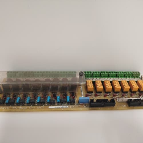
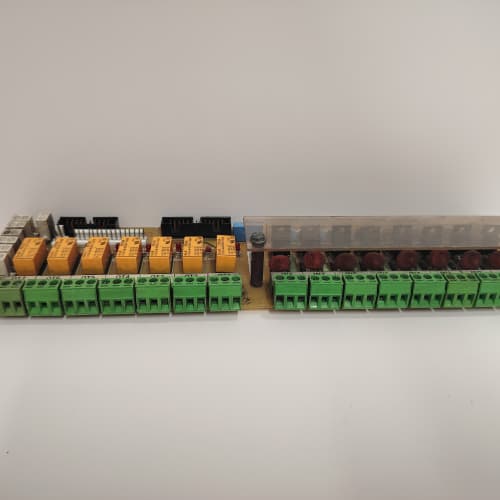
Bearing temperatures are the canary in the coal mine for turbine health. The 531X100CCHARM1 is the RTD input board that keeps an eye on them. This eight-channel module converts resistance signals from Pt100 sensors into temperature data the Mark V CPU can use for monitoring, alarms, and protection logic.
Compared to the 531X100CCHAR (non-M1 revision), the “M1” version incorporates two meaningful changes: the excitation current was reduced from 1mA to 500µA, cutting self-heating error in half for small sensors. The input protection was also upgraded with improved ESD clamping diodes. The terminal assignment is identical—direct drop-in. No firmware changes required.
Key Technical Specifications
| Parameter | Value / Range |
|---|---|
| Number of Inputs | 8, individually isolated |
| RTD Types Supported | Pt100, Ni120 (software-selectable per channel) |
| Configuration | 3-wire (default), 4-wire (selectable) |
| Excitation Current | 500 µA (constant) |
| Resolution | 16-bit (0.003°C for Pt100) |
| Accuracy (Overall) | ±0.1°C at 25°C, ±0.3°C over full operating range |
| Input Range | 0 to 400Ω |
| Lead Resistance Compensation | Up to 25Ω (3-wire) |
| Conversion Time | 200 ms per channel (sequential) |
| Open-Circuit Detection | Yes—flags as fault when >1000Ω |
| Common-Mode Rejection | > 90 dB at 50/60 Hz |
| Isolation (Channel-to-GND) | 1500 VAC |
| Status LEDs | Power (green), Fault (red), Communication (flashing) |
| Termination | 2 x 18-pin spring-clamp terminal blocks |
| Coating | Conformal-coated |
| Power Supply | 24 VDC from backplane (isolated) |
| Operating Temp | 0°C to +60°C |
| Dimensions (W x H x D) | 280 x 120 x 40 mm (11.0 x 4.7 x 1.6 in) |
Compatible Replacement Models
| Model | Classification | Notes & Labor Estimate |
|---|---|---|
| 531X100CCHARM1 | ✅ Drop-in Replacement | Target model. Same form factor and terminal block. No changes. |
| 531X100CCHAR | ✅ Drop-in Replacement | Earlier revision—1mA excitation current. Direct swap; you get lower self-heating with the M1. |
| 531X100CCHAPM1 | ❌ Hardware Incompatible | Current input board (4-20mA), not RTD. Different application and wiring. |
| DS4820B1SA | ✅ Drop-in Replacement | Equivalent Mark V RTD board with identical specs. Direct swap—verify part number compatibility. |
| IS420UIOBH4A | ❌ Hardware Incompatible | Mark VIe universal I/O module—different architecture. Not compatible. |
Frequently Asked Questions (FAQ)
Q: How do I wire a 3-wire Pt100 to the 531X100CCHARM1?
Connect the sensor’s excitation wire (usually red) to the Ex+ terminal for the channel. Connect the two sense wires (usually white) to the Input+ and Input- terminals. The board doesn’t care which sense wire goes where—it measures the differential voltage to compensate for lead resistance. For channel 1: terminal 1 (Ex+), terminal 2 (Input+), terminal 3 (Input-). If you mix up the excitation and sense wires, you’ll get an open-circuit reading. We’ve seen this happen frequently—mark your wires before disconnecting the old board.
Q: What’s the self-heating effect with the 500µA excitation current?
Self-heating is I²R = 0.0005² × 100 = 25µW, which translates to about 0.02°C temperature rise in a typical Pt100 sensor. The older 1mA excitation caused 100µW and about 0.05°C self-heating. For bearing temperature monitoring (where a 0.5°C difference can indicate a developing problem), the M1’s lower excitation is a meaningful improvement. The tradeoff is slightly longer conversion time—but the board compensates by using a more sensitive ADC.
Q: The reading is showing open-circuit on channel 4, but the RTD is connected. What should I check?
The board detects an open when the resistance exceeds 1000Ω. A corroded terminal, a loose crimp at the sensor head, or a broken lead wire can cause this. Use an ohmmeter to measure between the Ex+ and Input+ terminals at the board—you should see the RTD’s resistance (around 100-150Ω at room temperature). If you measure open, trace back to the sensor. If you measure the correct resistance but the board still shows open, the input multiplexer may have failed. Try a different channel to isolate the issue.
Q: What’s the total scan time for all 8 channels?
The board converts one channel at a time, with a conversion time of 200ms per channel. The total scan time for all 8 channels is 1.6 seconds. That’s fine for temperature signals—they change slowly. If you need faster updates, you can reduce the conversion time to 100ms (total 800ms) or 50ms (total 400ms) in the I/O map, but the noise will increase. For most turbine applications, 1.6 seconds is acceptable for bearing temperature monitoring.
Q: Does the 531X100CCHARM1 support 4-wire RTDs?
Yes—the board can be configured for 4-wire RTDs on a per-channel basis. In 4-wire mode, the excitation current flows through two wires, and the sense wires carry negligible current—this completely eliminates lead resistance error. To wire a 4-wire RTD, connect the excitation pair to Ex+ and 0V return, and the sense pair to Input+ and Input-. Check GE’s manual GEK-108756 for the exact pinout. We’ve seen many plants using 3-wire mode when 4-wire would be better for long cable runs.
Q: The fault LED is flashing red. What does that indicate?
Flashing red indicates a communication loss with the CPU over the backplane. Reseat the board firmly. If the fault persists, try the board in a known-good slot. If it works there, the original slot has a backplane issue (bent pin or failed backplane). If it fails in the good slot, the board’s backplane interface may be faulty—this is a common failure after power surges.
Q: Can I use the 531X100CCHARM1 with Pt1000 sensors?
No—the board only supports Pt100 and Ni120. Pt1000 sensors have 10x the resistance, which would saturate the ADC (the board’s input range is 0-400Ω). If you need Pt1000 support, you’ll need the DS4815PRTA (or equivalent). Some plants have tried adding external resistors in parallel to scale the resistance down—that introduces accuracy errors and isn’t recommended.
Q: What’s the maximum cable length for RTD inputs?
The board’s lead resistance compensation is rated for up to 25Ω per lead. With 18 AWG copper wire (0.006Ω/ft), that’s about 4100 feet (1250m) per lead. In practice, we recommend keeping it under 500 feet to minimize noise pickup. Use shielded twisted-pair cable and ground the shield at the rack end only. We’ve seen 1000-foot runs work with 18 AWG, but noise becomes an issue if the cable runs near VFDs or high-voltage lines.
Q: Can I hot-swap the 531X100CCHARM1 while the turbine is running?
The backplane supports live insertion, but we don’t recommend it. RTD sensors are wired directly to the board—pulling the board breaks the excitation current and can cause open-circuit faults that might trigger alarms. Also, inserting the board while the sensors are connected can cause a momentary voltage spike on the sensor leads, potentially damaging the sensor (unlikely, but possible). For critical bearing temperature monitoring, schedule a planned outage.
Q: What’s the lead time for a surplus unit?
We keep 4-6 units in stock. Domestic: 2-3 business days ground, overnight if ordered by 2 PM EST. International: 5-7 days via DHL, with customs potentially adding 1-3 days. This board is not ITAR-controlled, so we can ship to most countries without an export license. We include a GE certificate of origin and commercial invoice with every shipment. Contact us if you need expedited shipping for a critical outage.
 NI PXI-2597
MOTOROLA MVME5100
ABB DSSR122M
SUETRON BT05AM/702030-01
 Email: sales@plcfcs.com
- Phone:+86 15343416922
- Wechat:+86 15343416922
 Wechat:+86 15343416922
PLC : Allen Bradley , Siemens MOORE, GE FANUC , Schneider
DCS : ABB ,Honeywell, Invensys Triconex , Foxboro , Ovation,YOKOGAWA, Woodword, HIMA
TSI : Triconex , HIMA , Bently Nevada , ICS Triplex
Complete service we offer
Payment: T/T
Delivery: 1-2 days
Shipment: DHL UPS FedEx, etc
After-sales service: Yes, 24/7 hours