 Email: jiedong@sxrszdh.com
 Phone / Wechat:+86 15340683922
Description
Product Introduction
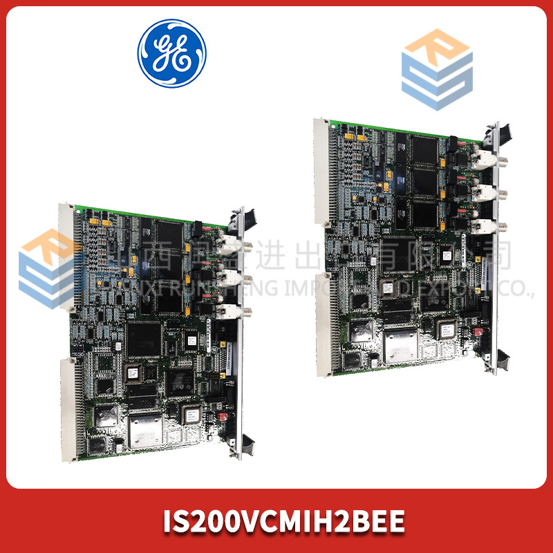
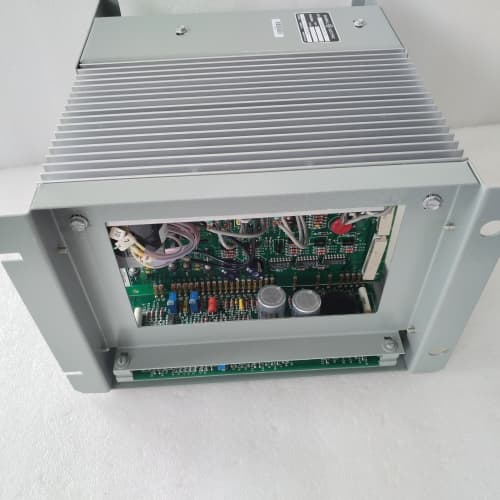
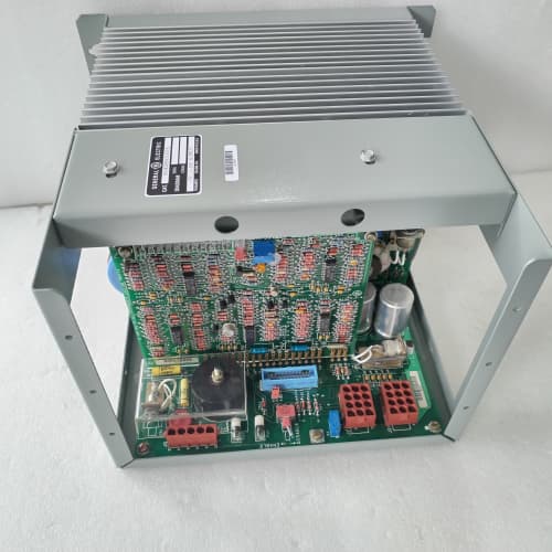
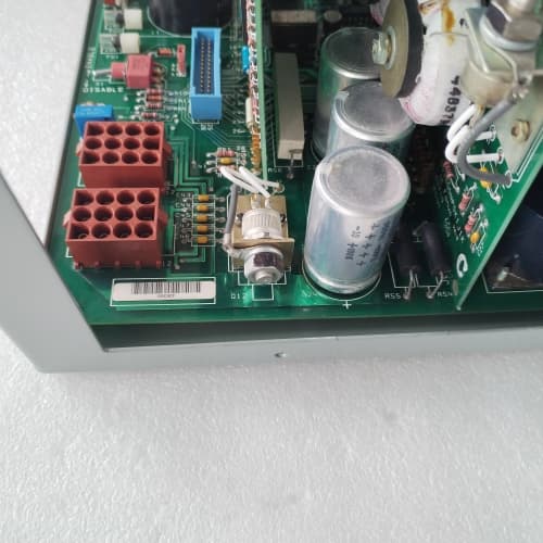
The DS3800XTBA1B1A is a variant of GE’s RTD input board designed specifically for 2-wire Pt100 sensors. The “B” in the suffix is the tell—instead of the 3-wire configuration of the standard XTBA (which gets an “A”), this version is factory-configured for 2-wire RTDs. That means it provides the excitation current and measures the voltage on the same two wires—no separate sense leads. If your plant has existing 2-wire installations or you’re working with sensors that only have two terminals, this board is the direct replacement.
Where this board differs from the 3-wire version is the input architecture and the trade-off: 2-wire measurement is simpler and uses less cabling, but it doesn’t cancel lead resistance. If your RTD sensors are close to the cabinet (short cable runs), that’s fine. If you’re running long distances, lead resistance will add directly to the measurement and cause an offset. The “1B1A” suffix also includes an acrylic conformal coating, so this board is protected against humidity and dust—a good choice for non-climate-controlled cabinets. Typical buyers are plant engineers with legacy 2-wire RTD installations or new projects where cable runs are short.
Key Technical Specifications
| Parameter | Value / Specification |
|---|---|
| Part Number | DS3800XTBA1B1A |
| Product Type | RTD Input Terminal Board |
| Input Channels | 8 (Differential) |
| Supported RTD Type | Pt100 (2-wire) |
| Excitation Current | 1 mA per channel (constant current source) |
| Input Range | 0 to 400Ω (covers -50°C to +850°C for Pt100) |
| Resolution | 16 bits |
| Accuracy | ±0.1% of reading ±0.5°C (excluding lead resistance error) |
| Lead Resistance Compensation | Not applicable (2-wire) |
| Diagnostics | Open-circuit detection, short-circuit detection, out-of-range detection |
| Input Impedance | >10 MΩ (with excitation disabled) |
| Isolation | 250 V RMS (Channel to Backplane) |
| Bus Interface | VME (Proprietary GE Mark VIe backplane) |
| Termination | 37-pin D-Sub female (Field side) |
| Power Draw | +5V DC @ 1.2A (typical) |
| Operating Temp | 0°C to 60°C |
| Suffix Meaning | 2-wire configuration, enhanced filtering, conformal coating |
Compatible Replacement Models
| Model | Compatibility | Notes |
|---|---|---|
| DS3800XTBA | ⚠️ Software Compatible | 3-wire version. Electrical drop-in but requires 3-wire sensors. If you have 2-wire sensors, this won’t work correctly. |
| DS3800XTB | ⚠️ Software Compatible | Earlier 2-wire version without enhanced filtering or coating. Direct electrical drop-in if you don’t need the coating. |
| DS3800XJBA | ❌ Hardware Incompatible | Thermocouple input board. Different front-end design—no excitation current. Not compatible. |
| DS3800XCMA | ❌ Hardware Incompatible | Different RTD type (3-wire). Not suitable for 2-wire sensors. |
Frequently Asked Questions (FAQ)
Q: Can I hot-swap this board?
No. The Mark VIe backplane does not support live insertion for RTD input boards. Power down the entire I/O pack before removal. We’ve seen field engineers try to hot-plug these and corrupt the excitation current calibration—the board reads off until a full recalibration.
Q: How is the 1B1A different from the standard XTBA?
Three differences:
- Wire configuration: The 1B1A is 2-wire; the standard XTBA is 3-wire. The pinout on the 37-pin D-Sub is different—you can’t just swap a 3-wire board into a 2-wire installation and expect it to work.
- Lead resistance compensation: The 2-wire version doesn’t cancel lead resistance. If your cable run is over 10 meters, the lead resistance adds directly to the RTD reading (roughly 0.04°C per ohm of lead resistance).
- Coating: The “A” suffix (at the end) indicates conformal coating. The standard XTBA (no suffix) has no coating.
The excitation current (1mA) and accuracy specs are the same. The physical footprint is identical.
Q: What’s the trade-off with 2-wire RTDs?
The 2-wire configuration is cheaper and uses less cable. But the lead wire resistance adds directly to the RTD resistance, causing a temperature offset. For example:
- 10 meters of 24 AWG copper wire has about 0.8Ω total loop resistance.
- For a Pt100, 0.8Ω equals about 2°C offset.
So if your sensors are close to the cabinet (under 10 meters), the error is manageable. If you have long runs, you’ll need to calibrate the offset in software or use the 3-wire version.
Q: How do you test this board before shipping?
We run a 7-step test with precision decade resistance boxes and a focus on the 2-wire configuration:
- Visual inspection: Check for cracked connectors, burnt traces, swollen capacitors. Inspect the coating for uniformity.
- ESD check: Insulation resistance between channels and chassis ground >10MΩ.
- Power-up: Apply +5V DC, measure current draw (1.2A ±10%).
- Communication handshake: Simulate backplane connection, verify board ID.
- Excitation verification: Measure the 1mA excitation current on each channel—must be within ±1%.
- RTD simulation: Connect a precision decade box to each channel and simulate resistances corresponding to 0°C (100Ω), 100°C (138.5Ω), and 200°C (175.8Ω). Verify accuracy within ±0.1% of reading ±0.5°C. Note that any lead resistance added by the test leads will be included in the measurement—we use short, heavy-gauge test leads to minimize this.
- 24-hour soak: Run at 50°C ambient with all channels at 100Ω. Log drift—failure threshold is ±0.5°C deviation.
We reject about 4% of these boards—typically due to excitation current drift.
Q: Can I use 3-wire RTDs with this board?
No. This board is designed for 2-wire RTDs. If you connect a 3-wire sensor, the third lead will be unused, and you’ll lose the lead resistance cancellation. You could wire it as a 2-wire sensor (using two of the three leads), but the lead resistance will add to the measurement. If you have 3-wire sensors, you need the standard XTBA (3-wire version).
Q: Can I use 4-wire RTDs with this board?
No. The board only supports 2-wire. If you have 4-wire sensors, you can wire them as 2-wire by shorting the sense leads to the drive leads at the sensor head—but you lose the benefits of the 4-wire configuration. For 4-wire, you’d need a different board (rare in Mark VIe applications).
Q: What’s the most common field issue with this board?
Lead resistance error. The 2-wire configuration means the lead wire resistance is measured as part of the RTD. If your cable run is long, the temperature reading will be high by a constant offset. The fix:
- Short cable runs: Keep the cable under 10 meters, and use heavy-gauge wire (24 AWG or thicker) to minimize lead resistance.
- Calibration offset: Measure the lead resistance (disconnect the RTD and short the wires at the sensor end), then apply a software offset in ToolboxST.
- Upgrade to 3-wire: If you’re running long distances and can’t calibrate out the error, consider upgrading to 3-wire RTDs and the standard XTBA.
Q: What’s the most common failure on this board?
Three things:
- Excitation current drift: The 1mA current sources are sensitive to temperature. We replace reference resistors on about 15% of refurbished units.
- Coating issues: On coated boards, we occasionally see contamination trapped under the coating. If the coating looks uneven or has bubbles, we reject it.
- Input protection diode burnout: If a field wiring fault puts 24V on the RTD input, the protection diodes can short.
Q: What does the “1B1A” suffix mean?
On GE’s Mark VIe RTD board naming:
- 1: Base design revision
- B: Wire configuration (2-wire)
- 1: Specific component batch
- A: Conformal coating (acrylic)
So this board has 2-wire support with conformal coating. If you need 3-wire support, look for “1A…” suffix (e.g., XTBA1A1A).
Q: My bearing temperature readings are 3°C high. Is this a board issue?
Check lead resistance first. With 2-wire RTDs, every ohm of lead resistance adds about 0.4°C error. Measure the lead resistance from the cabinet to the sensor and back. If it’s more than 1Ω, you’ll see error. Other possibilities:
- Excitation current drift (requires a bench test)
- Terminal oxidation (clean the D-Sub pins)
If the lead resistance is low and the terminals are clean, the board’s calibration might have drifted. We can recalibrate it on our test rig.
Q: Are there counterfeit versions of this board?
Yes. Look for:
- Reference resistors: Genuine boards use 0.1% precision resistors. Counterfeits use 1% resistors—the excitation current drifts with temperature.
- Coating: Genuine coating is uniform, matte, slightly yellowish. Fakes use cheaper lacquer.
- Label: Genuine—matte finish, greenish barcode. Fakes—glossy.
- Weight: Genuine board weighs 225g ±5g. Fakes are lighter.
We trace stock to decommissioned assets. If buying elsewhere, demand photos of the component side and serial sticker.
Q: What’s your warranty?
1-year against functional defects. For RTD boards, we also guarantee the excitation current accuracy for the warranty period—if it drifts out of spec, we’ll replace it.
Q: What’s the lead time?
We typically carry 2-4 units. Orders before 2 PM EST ship within 1-2 business days after testing. The 24-hour soak is non-negotiable—we won’t skip it. Expedited shipping available with waiver (you acknowledge the long-term soak was skipped). For critical bearing temperature monitoring, we recommend waiting for the full test cycle—the excitation current only shows thermal drift after hours of operation.
GESPAC GESSBS-41T16N
ABB PPC905AE101
Prosoft MVI69E-MBS
 Email: sales@plcfcs.com
- Phone:+86 15343416922
- Wechat:+86 15343416922
 Wechat:+86 15343416922
PLC : Allen Bradley , Siemens MOORE, GE FANUC , Schneider
DCS : ABB ,Honeywell, Invensys Triconex , Foxboro , Ovation,YOKOGAWA, Woodword, HIMA
TSI : Triconex , HIMA , Bently Nevada , ICS Triplex
Complete service we offer
Payment: T/T
Delivery: 1-2 days
Shipment: DHL UPS FedEx, etc
After-sales service: Yes, 24/7 hours