
")
")
")
 Email: jiedong@sxrszdh.com
 Phone / Wechat:+86 15340683922
Description

Product Core Brief
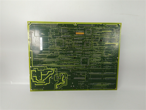
- Model: DS200RTBAG3AHC
- Brand: General Electric (GE)
- Series: Mark V DS200
- Core Function: Hybrid triple-bank relay board with mixed technologies
- Product Type: Hybrid Relay Board (48 channels, 3 banks)
- Key Specs: Bank A: 16 mechanical (10 A) | Bank B: 16 mechanical (5 A) | Bank C: 16 SSR (2 A fast) | 3 isolated banks
- Condition: New Original.
Product Introduction
The DS200RTBAG3AHC is a hybrid relay output termination board for GE’s Mark V DS200 series, used in Speedtronic turbine control systems. It provides 48 outputs across three isolated banks with different relay technologies: Bank A (16 mechanical relays, 10 A high current), Bank B (16 mechanical relays, 5 A general purpose), and Bank C (16 solid state relays, 2 A, <100 µs fast switching).
The “3AHC” suffix indicates a triple-bank hybrid configuration—the most versatile RTBA board in the family. It is designed for applications requiring a mix of load types: heavy motor starters (Bank A, 10 A), general purpose solenoids and indicators (Bank B, 5 A), and high-speed PWM control or silent switching (Bank C, SSR). All on one board, one rack slot, with bank-to-bank isolation.
Key Technical Specifications
| Parameter | Bank A (High Power Mech) | Bank B (Std Mech) | Bank C (SSR) |
|---|---|---|---|
| Number of outputs | 16 (relays 1–16) | 16 (relays 17–32) | 16 (channels 33–48) |
| Output type | Mechanical, Form C | Mechanical, Form C | SSR, Form A (SPST-NO) |
| Contact rating (resistive) | 10 A @ 250 VAC / 30 VDC | 5 A @ 250 VAC / 30 VDC | 2 A @ 280 VAC / 60 VDC |
| Contact rating (inductive) | 5 A @ 250 VAC / 30 VDC | 2 A @ 250 VAC / 30 VDC | 1 A @ 250 VAC |
| Switching time | 15 ms typical | 10 ms typical | <100 µs (DC), <8.3 ms + ZC (AC) |
| Max switching frequency | 10 Hz | 20 Hz | 1 kHz (DC), 120 Hz (AC) |
| Electrical life | 50k cycles at 10 A | 100k cycles at 5 A | Unlimited (100M cycles) |
| Minimum load | 100 mA @ 12 VDC | 100 mA @ 12 VDC | None (leakage applies) |
| Terminal type | Fixed screw (10–18 AWG) | Removable screw (12–24 AWG) | Removable pluggable (12–24 AWG) |
| Per-channel indication | Red + Green LED | Red + Green LED | Green LED (input signal) |
| Coil/input current | 30 mA per relay | 15 mA per relay | 5 mA per channel |
Shared Parameters (All Banks)
| Parameter | Value | |||
|---|---|---|---|---|
| Coil/input voltage | 24 VDC nominal (from backplane) | |||
| Total backplane current | Bank A: 480 mA | Bank B: 240 mA | Bank C: 80 mA | Total: 800 mA max |
| External coil power option | Bank A only (requires 480 mA) | None (runs from backplane) | N/A (SSR, no coil) | |
| Coil suppression | RCD snubber (Bank A), Diode (Bank B) | N/A | ||
| Protection (SSR Bank C) | Snubber (AC) or TVS (DC) per channel | |||
| Bank-to-bank isolation | 2500 VAC for 1 minute (between any two banks) | |||
| Operating temperature | −30°C to +60°C | |||
| Dimensions | 420 mm x 240 mm x 65 mm | |||
| Weight | 3.2 kg (7.1 lbs) | |||
| Accessories included | External coil power jumper (Bank A), spare terminal blocks (Bank B & C, 2 sets each), spare relay (Bank A, 1), labeling strips, thermal pad kit (for Bank A), torque card, AC/DC mode jumper (Bank C) |
Key Selling Points & Differentiators
- Three technologies, one board, one slot – Bank A: 10 A mechanical for heavy loads. Bank B: 5 A mechanical for general purpose. Bank C: 2 A SSR for high-speed/silent switching. No need for three separate boards. Saves two rack slots.
- Bank A (10 A high power, fixed terminals) – Switch motor starters (1 HP), large solenoids, pump contactors, heater banks. Fixed screw terminals rated for 10 AWG. Bifurcated silver-tin oxide contacts. Red + green LEDs for contact verification. External coil power option available.
- Bank B (5 A general purpose, removable terminals) – Switch smaller solenoids, relay coils, indicator lights, annunciators. Removable screw terminal blocks for easy rewiring. Standard silver alloy contacts. Red + green LEDs. Runs from backplane power (240 mA total).
- Bank C (2 A SSR, fast switching, silent) – PWM control of heaters, high-speed valve arrays, lamp testing, LED panels. Zero-crossing AC or random-turn-on DC (field selectable). Removable pluggable terminal blocks. Unlimited mechanical life. No coil current—only 5 mA input per channel.
- Triple bank-to-bank isolation at 2500 VAC – Bank A, Bank B, and Bank C are fully isolated. Connect Bank A to 240 VAC pumps, Bank B to 120 VAC solenoids, Bank C to 24 VDC fast valves on the same board. No ground loops.
- Mixed terminal types optimized per bank – Bank A: fixed screw (high current). Bank B: removable screw (convenience). Bank C: removable pluggable (fast rewiring for high-cycle applications).
- QC includes separate load tests per bank type – Bank A: 10 A resistive, 24 hours. Bank B: 5 A resistive, 10,000 cycles. Bank C: 1 kHz cycling, 1,000,000 cycles. Bank-to-bank isolation at 3000 VAC.
- 2-year warranty – Covers all 48 outputs across all three technologies, monitoring (where applicable), external coil power circuit (Bank A), and any manufacturing defect.
Frequently Asked Questions (FAQ)
Q: Why would I choose the hybrid RTBAG3AHC instead of separate dedicated boards?
| Scenario | Separate Boards | Hybrid (3AHC) |
|---|---|---|
| Rack slots needed | 3 slots | 1 slot |
| Backplane current | Up to 1.5 A | 0.8 A |
| Cabinet space | 3x board area | 1x board area |
| Wiring complexity | Three sets of field wires | One set (segregated by bank) |
| Cost | Higher (three boards) | Lower (one board) |
| Mixed technology | Requires external wiring | Integrated |
Choose hybrid when your application requires a mix of load types (heavy, light, fast) and rack space is limited.
Q: Can I replace three separate RTBA boards (one 10 A, one 5 A, one SSR) with one 3AHC without changing my Mark V configuration?
A: Partially. The relay numbering on the 3AHC is sequential: relays 1–16 (Bank A, 10 A), relays 17–32 (Bank B, 5 A), channels 33–48 (Bank C, SSR). Your existing three boards likely had overlapping numbers (each had relays 1–16). You will need to:
- Remap your Mark V output bits to the new sequential numbering (e.g., old Board 2 relay 1 becomes new relay 17).
- Re-land field wires (144 total) onto the 3AHC terminals. Bank A uses fixed terminals, Banks B and C use removable blocks.
- Reprogram logic to account for different contact forms (Bank C is Form A, no NC contact).
Allow 10–16 hours for conversion. We provide a conversion worksheet.
Q: How do I use the external coil power option for Bank A?
A: Bank A (10 A mechanical relays) draws 480 mA when all 16 relays are energized. If your backplane 24 VDC is limited, move the jumper on Bank A (near the ribbon cable header) to “EXT” position. Connect an external 24 VDC supply (1 A minimum) to the 2-position terminal block labeled “EXT 24V+ / EXT 24V-“. Bank B and Bank C run from backplane power only (no external option). The Mark V output module still controls Bank A relays via opto-isolation.
Q: Can Bank C (SSR) be configured for AC or DC?
A: Yes. Bank C has four groups of 4 channels (33–36, 37–40, 41–44, 45–48). Each group has a 2-position jumper. For AC (zero-crossing), install the jumper. For DC (random turn-on), remove the jumper. Default from factory: Group 1 & 2 = AC, Group 3 & 4 = DC. Change jumpers before installing the board. Do not change with power applied.
Q: What are the thermal limitations for each bank?
A: Bank A (10 A mechanical): 10 A on all 16 relays simultaneously requires panel mounting (thermal pad to metal surface) AND forced air cooling (200 LFM). Without forced air, limit to 5 A per relay. Bank B (5 A mechanical): 5 A on all 16 relays OK with panel mounting; DIN rail OK for 3 A average. Bank C (SSR): 2 A on all 16 channels (32 A total) not possible—thermal limit 16 A total per bank (1 A average) with panel mounting. Derating chart included.
Q: The board has three different terminal types. How do I replace damaged ones?
A: Bank A (fixed screw terminals): cannot replace in field—return for repair ($65 + shipping). Bank B (removable screw blocks): squeeze latches and pull straight up. Spare blocks included. Bank C (removable pluggable blocks): same as Bank B. We sell spare blocks for Bank B (part ACC-TRM-RTB-B) and Bank C (part ACC-TRM-SSR).
Q: What is the green LED function on Bank A and Bank B?
A: Red LED = coil energized (command from output module). Green LED = contact closed AND field voltage present on Common (C) terminal. Sense voltage range: 12–250 VAC or 12–125 VDC. If you do not want the green LED, leave C terminal unconnected—relay still switches, but LED stays off. Bank C (SSR) has only green LED (input signal present).
Q: Can Bank A switch 240 VAC at 10 A continuously?
A: Yes, resistive loads (heaters, incandescent lamps). For inductive loads (motors, solenoids) at 240 VAC, derate to 5 A. A 1 HP motor at 240 VAC draws 4 A running but 25 A inrush. The inrush will weld Bank A contacts. Use Bank A to control an external contactor for motor loads. Bank A is rated for contactor coils (5–10 VA).
Q: What QC tests are specific to the hybrid 3AHC revision?
A: Fifteen tests, separated by bank technology:
Bank A (10 A Mechanical):
- Coil resistance: 800Ω ±3%. Contact resistance: <30 mΩ at 1 A.
- Load test: 10 A resistive, 24 hours, all 16 relays.
- External coil power test: Verify jumper operation.
Bank B (5 A Mechanical):
- Coil resistance: 1.6 kΩ ±3%. Contact resistance: <50 mΩ at 100 mA.
- Load test: 5 A resistive, 10,000 cycles (sample of 8 relays).
Bank C (SSR):
- Input current: 5 mA ±1 mA per channel.
- Turn-on/off time (DC): <100 µs. Oscilloscope capture.
- On-state voltage drop: <1.5 VAC at 2 A, <1.0 VDC at 2 A.
- High-cycle test: All 16 channels at 1 kHz (DC) for 1,000,000 cycles.
All Banks:
- Bank-to-bank isolation: 3000 VAC between A-B, B-C, A-C.
- Input-to-output isolation per bank: Bank A/B: 3000 VAC; Bank C: 5000 VAC.
- Operate/switching test: 500 cycles each.
- Thermal imaging: Mixed loads per bank rating for 2 hours with panel mounting.
- LED tests: Bank A/B: red+green; Bank C: green.
- Ribbon cable test: All three 64-pin shielded cables.
Q: What shipping protection for this large heavy hybrid board?
A: The 3AHC weighs 3.2 kg (7.1 lbs). Anti-static bag, custom ESD foam cradle with separate cutouts for Bank A fixed terminals (48 positions), Bank B removable blocks (32 positions), Bank C removable blocks (32 positions), and three ribbon cable headers. Bank B and C removable blocks shipped installed to protect pin headers. Thermal pad kit (required for Bank A loads >5 A average) in separate sealed bag. Double-wall box with “HEAVY,” “FRAGILE,” “ESD SENSITIVE,” “DO NOT STACK” labels. Shock indicator on outside. Each board ships individually. Hybrid configuration guide (8 pages) included as printed document.

77456-01 PLC DCS
722010202050 PLC DCS
22010202 PLC DCS
 Email: sales@plcfcs.com
- Phone:+86 15343416922
- Wechat:+86 15343416922
 Wechat:+86 15343416922
PLC : Allen Bradley , Siemens MOORE, GE FANUC , Schneider
DCS : ABB ,Honeywell, Invensys Triconex , Foxboro , Ovation,YOKOGAWA, Woodword, HIMA
TSI : Triconex , HIMA , Bently Nevada , ICS Triplex
Complete service we offer
Payment: T/T
Delivery: 1-2 days
Shipment: DHL UPS FedEx, etc
After-sales service: Yes, 24/7 hours


