")
")
")
 Email: jiedong@sxrszdh.com
 Phone / Wechat:+86 15340683922
Description

Product Core Brief
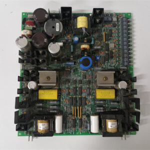
- Model: DS200RTBAG3AEB
- Brand: General Electric (GE)
- Series: Mark V DS200
- Core Function: High-power triple-bank relay board with 10 A contacts
- Product Type: High Power Relay Board (48 channels, 3 banks)
- Key Specs: 48 Form C relays | 10 A contacts | Three isolated banks | Fixed screw terminals
- Condition: New Original.
Product Introduction
The DS200RTBAG3AEB is a high-power relay output termination board for GE’s Mark V DS200 series, used in Speedtronic turbine control systems. It provides 48 independent Form C relay outputs rated for 10 A continuous, arranged as three isolated banks of 16 relays each—combining the high current capacity of the RTBAG1AEB with the channel density of the RTBAG3 platform.
The “3AEB” suffix indicates a triple-bank high-power board. This is essentially three RTBAG1AEB boards integrated onto a single PCB with bank-to-bank isolation. It is designed for heavy industrial applications requiring direct switching of multiple high-current loads: 48 motor starters (1 HP each), pump contactors, large solenoid valves, heater banks, and other 10 A loads—all in a single rack slot.
Key Technical Specifications
| Parameter | Value |
|---|---|
| Number of relay outputs | 48 (3 banks of 16) |
| Bank A relays | Relays 1–16 |
| Bank B relays | Relays 17–32 |
| Bank C relays | Relays 33–48 |
| Relay type | Electromechanical, Form C (SPDT), bifurcated silver-tin oxide contacts |
| Contact arrangement | Common (C), Normally Open (NO), Normally Closed (NC) per relay |
| Contact rating (resistive) | 10 A @ 250 VAC, 10 A @ 30 VDC |
| Contact rating (inductive) | 5 A @ 250 VAC (cosφ = 0.4), 5 A @ 30 VDC (L/R = 40 ms) |
| Maximum switching voltage | 250 VAC, 125 VDC |
| Maximum switching current | 10 A |
| Maximum switching power | 2500 VA, 300 W |
| Minimum switching load | 100 mA @ 12 VDC (bifurcated contacts) |
| Coil voltage | 24 VDC nominal (selectable: backplane or external supply per bank) |
| Coil current per relay | 30 mA ±3 mA at 24 VDC |
| Total backplane current (internal power mode) | 1440 mA (48 x 30 mA) |
| External coil power option | Per bank jumper selectable; use external 24 VDC supply (8 A minimum for full bank) |
| Coil suppression | RCD snubber (diode + 470 nF + 47Ω) across each coil |
| Per-channel indication | Red LED (coil energized) + Green LED (contact closed, field power sense) |
| Per-bank status | Power LED (bank enabled), Overload LED (bank current >16 A or overtemperature) |
| Contact material | Silver-tin oxide (AgSnO2) with bifurcated (twin) contacts |
| Mechanical life | 10,000,000 operations (no load) |
| Electrical life (10 A resistive) | 50,000 operations |
| Electrical life (5 A inductive) | 25,000 operations |
| Operating time | 15 ms typical |
| Release time | 8 ms typical |
| Isolation (bank-to-bank) | 2500 VAC for 1 minute |
| Isolation (coil to contacts per bank) | 2500 VAC for 1 minute |
| Terminal type | Fixed heavy-duty screw terminal, rising cage, 10–18 AWG (not removable) |
| Terminal torque | 0.8–1.0 Nm (7–9 lb-in) |
| Connection to output modules | Three 64-pin ribbon cables (one per bank, included, shielded) |
| External coil power connector | Three 2-position terminal blocks (1 per bank, 10–18 AWG) |
| Operating temperature | −30°C to +60°C (derate to 7 A at +60°C, 5 A at +70°C) |
| Storage temperature | −40°C to +85°C |
| Dimensions | 420 mm x 240 mm x 65 mm |
| Weight | 3.5 kg (7.7 lbs) |
| Accessories included | External coil power jumpers (pre-installed to backplane power), spare relays (3, field replaceable with soldering), labeling strips (1–48), torque card, thermal pad kit (for panel mounting), bank identification labels, DIN rail end clips (6) |
Key Selling Points & Differentiators
- 48 high-current relays in one slot – Three independent banks of 16 relays each, rated 10 A continuous. Replaces three RTBAG1AEB boards and saves two rack slots. Directly switch 48 motor starters, pumps, or heater contactors. No external interposing relays needed for most applications.
- Per-bank external coil power option – Standard backplane 24 VDC may not have 1440 mA available for all 48 coils. Move a jumper per bank to use an external 24 VDC supply (8 A minimum per bank for full 16 relays energized). Relays still controlled by Mark V output modules; only coil power comes from external source. Essential for heavily loaded backplanes.
- Bifurcated (twin) contacts on all 48 relays – Each contact has two parallel touching surfaces. Reduces contact resistance by 50% and provides redundancy. Rated for 100 mA minimum load (versus 500 mA on standard power relays). Reliable switching even at low currents.
- Dual LED status per channel – Red LED = coil energized (command from output module). Green LED = contact closed AND field voltage present. Green LED requires field power sense (24–250 VAC/DC). Instant verification that the contact actually closed and field power is available.
- Per-bank overload monitoring – Yellow LED lights per bank when total current through all 16 relays exceeds 16 A or bank temperature exceeds 85°C. Warning only—does not disable outputs. Each bank has a Form C alarm relay (1 A rating) for remote monitoring.
- Fixed screw terminals rated for 10 A continuous – Removable terminal blocks cannot safely handle 10 A long-term. The AEB uses fixed rising cage terminals with 6 mm² wire capacity (10 AWG). Torque to 0.9 Nm.
- Triple bank-to-bank isolation at 2500 VAC – Connect Bank A to 240 VAC pumps, Bank B to 120 VAC motor starters, and Bank C to 24 VDC solenoids on the same board. No ground loops.
- QC includes 24-hour 10 A load test on all 48 relays – Every relay runs at 10 A resistive, 30 VDC for 24 hours continuous. Contact resistance measured at 0, 1, 2, 4, 8, 12, 24 hours. Final <100 mΩ. Thermal imaging verifies no hot spot >85°C.
- 2-year warranty – Covers contact welding, coil failure, LED failure, external coil power circuit, overload monitoring, or any manufacturing defect on any bank.
Frequently Asked Questions (FAQ)
Q: What’s the difference between RTBAG3A (5 A standard), RTBAG3AEB (10 A high power), and RTBAG3ABB (5 A high reliability)?
| Feature | RTBAG3A (Standard) | RTBAG3AEB (High Power) | RTBAG3ABB (High Rel) |
|---|---|---|---|
| Contact rating | 5 A | 10 A | 5 A |
| Coil current (all 48) | 720 mA | 1440 mA (or external) | 720 mA |
| Terminal type | Removable screw | Fixed screw | Removable screw (gold pins) |
| Green LED (contact sense) | No | Yes | No |
| Overload monitoring | No | Yes (per bank) | No |
| External coil power | No | Yes (per bank) | No |
| Contact material | Silver alloy | Bifurcated AgSnO2 | Gold-flashed AgNi |
| Relay enclosure | Vented | Vented | Argon-sealed |
| Typical application | General purpose | Heavy loads (10 A) | Corrosive/low-level |
Choose AEB for loads above 5 A up to 10 A. Do not use AEB for low-level signals (<100 mA)—use ABB instead.
Q: Can I replace a standard RTBAG3A (5 A) with the AEB (10 A) without changing my Mark V configuration?
A: Yes—electrically, the pinout is identical. However:
- The AEB uses fixed screw terminals, not removable blocks. You will need to re-land all 144 field wires. Allow 8–12 hours.
- The AEB is physically larger (420 mm x 240 mm vs 420 mm x 220 mm). Verify cabinet height clearance.
- Coil current is 1440 mA versus 720 mA. Your backplane may need the external coil power option (see next question).
- The AEB requires 10 AWG wire for loads above 5 A. The standard board used 14–16 AWG typical.
Q: How do I choose between backplane coil power and external coil power for each bank?
A: Calculate your backplane 24 VDC load. List all modules: CPU (500 mA), each I/O module (100–300 mA), communication boards (200–400 mA). The RTBAG3AEB draws 480 mA per bank (16 x 30 mA) if all relays in a bank are energized simultaneously from the backplane. Total possible draw = 1440 mA. Mark V power supplies (DS200PCCAG series) typically provide 2–5 A on the 24 VDC rail. If total exceeds 80% of supply rating, use external coil power for one or more banks. We provide a load calculation worksheet. For maximum backplane headroom, power all three banks externally.
Q: How do I wire external coil power per bank?
A: Each bank has a dedicated 2-position terminal block (labeled “EXT 24V+” and “EXT 24V-“). Remove the jumper shunt from the backplane power header (located near the terminal block). Connect an external 24 VDC supply to the terminals:
- Bank A requires 480 mA minimum when all 16 relays energized. Use a 1 A supply minimum.
- Bank B same.
- Bank C same.
You can use one large 5 A supply for all three banks (parallel wiring). The Mark V output module still provides the control signal (opto-isolated). The external supply powers only the relay coils. Polarity matters.
Q: What is the green LED sense voltage range?
A: The green LED illuminates when the relay contact is closed (NO to C) AND field voltage is present on the Common (C) terminal. Sense voltage range: 12–250 VAC or 12–125 VDC. The LED is bidirectional (works with AC or DC). If you do not want the green LED, leave the C terminal unconnected—the relay still switches, but LED stays off. The green LED draws <2 mA and does not affect load current.
Q: The board has per-bank overload monitoring. What triggers the yellow LED?
A: Two conditions per bank. First: total current through all 16 relays in the bank exceeds 16 A (sum of individual channel loads). Second: bank temperature (measured by thermistor on PCB) exceeds 85°C. The yellow LED lights but does not disable outputs—it is a warning only. Each bank also has a Form C alarm relay (rated 1 A @ 24 VDC) that closes when either condition occurs. Wire this to a PLC input for remote alarming.
Q: Can I use the AEB for 240 VAC motor loads (1 HP, 4 A running, 25 A inrush)?
A: Yes, but with an external contactor. The AEB contacts are rated for 5 A inductive at 250 VAC. A 1 HP motor at 240 VAC draws 4 A running but 25 A inrush. The inrush will weld the AEB contacts within a few starts. Use the AEB to control a properly sized contactor (e.g., 25 A NEMA size). The AEB switches the contactor coil (5–10 VA, well within rating). We sell suitable contactors (part MTR-CONT-25A). For resistive loads (heaters) at 10 A, direct switching is fine.
Q: The AEB has fixed screw terminals. How do I replace a damaged terminal?
A: You cannot—the terminals are soldered to the PCB. If a terminal strip is damaged (bent, cracked, stripped threads), return the board for repair. We replace individual terminals ($65 + return shipping) due to the high current rating (requires reinforced soldering). For field repair, we sell a terminal repair kit (part ACC-TRM-REPAIR-HD) that includes a drill bit, replacement terminal, and high-temperature epoxy. Most plants keep a spare AEB board instead of attempting field repair—downtime is more expensive.
Q: What are the thermal mounting requirements?
A: The AEB draws significant current (up to 10 A per relay, 160 A total theoretical if all relays at 10 A—but thermally impossible). Practical maximum: 16 A total per bank (1 A average per channel) without forced air. For loads above 1 A per channel average, you MUST panel mount the board using the included thermal pad to a metal backplate (3 mm minimum thickness). For 5 A per channel average (80 A total per bank—not possible), forced air cooling (400 LFM) is required. Real-world: typical installation with mixed loads (some 5 A, some 1 A) works with panel mounting. Thermal derating chart included.
Q: What QC tests are specific to the AEB revision?
A: Thirteen tests, all documented:
Bank-specific:
- Coil resistance: 800Ω ±3% (30 mA).
- Contact resistance: <30 mΩ at 1 A, four-wire.
- External coil power test: Verify jumper operation per bank.
- Overload monitor test: Apply 17 A total to one bank, verify yellow LED and alarm relay within 10 seconds.
- Green LED sense test: Apply 24 VDC, 120 VAC, 250 VAC to C terminal.
All banks:
- Bank-to-bank isolation: 3000 VAC for 5 seconds between A-B, B-C, A-C. Leakage <0.5 mA.
- Coil-to-contacts isolation: 3000 VAC for 5 seconds.
- Operate test: Cycle each relay 500 times at 2 Hz.
- Load test (all 48 relays): 10 A resistive at 30 VDC, 24 hours continuous. Contact resistance measured at intervals. Final <100 mΩ.
- Inductive load test (sample of 9 relays, 3 per bank): 5 A at 30 VDC, L/R = 40 ms, 25,000 cycles.
- Thermal imaging: Full rated load (derated per bank based on typical application) for 2 hours with panel mounting. Hot spots <85°C.
- Terminal torque verification: All 144 terminals torqued to 0.9 Nm, logged.
- Vibration (sample lot): 5 Grms, 10–500 Hz, 2 hours per axis. No loose hardware, no contact resistance change >5 mΩ.
Q: What shipping protection for this heavy high-power board?
A: The AEB weighs 3.5 kg (7.7 lbs)—heaviest RTBA variant. Maximum protection: anti-static bag, custom-molded ESD foam cradle with cutouts for all 144 fixed screw terminals and three ribbon cable headers, hard plastic clamshell case with foam liner. Double-wall box with “HEAVY,” “FRAGILE,” “ESD SENSITIVE,” “DO NOT STACK,” and “THIS SIDE UP” labels. Shock indicator and tilt indicator on outside. Each board ships individually. Thermal pad kit (required for loads >1 A per channel average) in separate sealed bag. Spare relays (3) in ESD bag inside the same box. Load calculation worksheet and thermal derating chart laminated and attached to outside of clamshell.

MSK060C-0600-NN-M1-UP1-NSNN PLC DCS
MSK050C-0600-NN-M1-UP1-NSNN PLC DCS
MSK070C-0150-NN-S1-UG0-NNNN PLC DCS
 Email: sales@plcfcs.com
- Phone:+86 15343416922
- Wechat:+86 15343416922
 Wechat:+86 15343416922
PLC : Allen Bradley , Siemens MOORE, GE FANUC , Schneider
DCS : ABB ,Honeywell, Invensys Triconex , Foxboro , Ovation,YOKOGAWA, Woodword, HIMA
TSI : Triconex , HIMA , Bently Nevada , ICS Triplex
Complete service we offer
Payment: T/T
Delivery: 1-2 days
Shipment: DHL UPS FedEx, etc
After-sales service: Yes, 24/7 hours