")
")
")
 Email: jiedong@sxrszdh.com
 Phone / Wechat:+86 15340683922
Description

Product Introduction
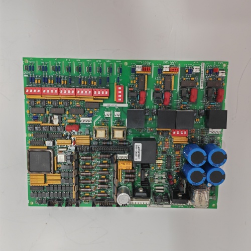
The DS200PTCTG1B is a current transformer termination board for GE’s Mark V DS200 series, used in Speedtronic turbine control systems. It provides a fixed 5 A interface for CT secondaries, using heavy-duty screw terminals designed for high-vibration environments.
Unlike the “A” revision which offered selectable 5 A or 1 A operation, the “1B” is fixed at 5 A. This eliminates any possibility of misconfiguration. The terminal blocks are upgraded from cage clamp to screw clamp with wire protectors—preferred in power generation applications where vibration can loosen spring terminals.
Key Technical Specifications
| Parameter | Value |
|---|---|
| Number of CT inputs | 8 (individually isolated) |
| CT secondary rating | 5 A fixed (no 1 A option) |
| Burden resistor | 0.1Ω ±0.1%, 5 W, wirewound |
| Output voltage at 5 A | 0.5 VAC nominal |
| Overload rating | 20 A continuous, 100 A for 1 second |
| Transient protection | MOV + TVS diode, clamping at ±12 V output |
| Isolation voltage | 1500 VAC input-to-output for 1 minute |
| Isolation resistance | >100 MΩ at 500 VDC |
| Frequency range | 45–65 Hz |
| Accuracy (5 A range) | ±0.2% from 0.5 A to 6 A |
| Phase shift | <0.5 degrees at 60 Hz, 5 A |
| Terminal type (CT side) | Heavy-duty screw clamp, 10–24 AWG, with wire protector (no ferrules needed) |
| Terminal type (output side) | Screw clamp, 16–24 AWG |
| Connection to I/O module | 16-pin ribbon cable (included) or direct screw terminal output |
| Operating temperature | −30°C to +70°C |
| Storage temperature | −40°C to +85°C |
| Power supply | None (passive) |
| Vibration rating | 5 Grms, 10–500 Hz (tested) |
| Dimensions | 200 mm x 130 mm x 45 mm |
| Accessories included | Shorting blocks (4, locking type), spare fuses (8 x 5 A, for external CT protection), labeling strips, mounting screws |
Key Selling Points & Differentiators
- Fixed 5 A operation – No jumpers, no configuration. If your CTs are 5 A secondary, this board works. Eliminates misconfiguration errors that plague selectable-range boards.
- Heavy-duty screw terminals with wire protectors – Designed for high-vibration turbine applications. Wire protector prevents strand breakage under the screw head. Terminals rated for 100 insertion/removal cycles.
- Locking shorting blocks included – Each block has a positive detent and a locking tab. Once in “SHORT” position, the block cannot vibrate open. Tested at 5 Grms for 2 hours—no movement.
- Simplified field wiring – Larger terminal pitch (12 mm vs 8 mm on the 1A) leaves room for gloved hands. Terminal numbers are embossed (not printed)—won’t wear off.
- No 1 A confusion – We’ve seen customers accidentally leave 1 A jumpers in place while feeding 5 A CTs, causing 5x overvoltage at the analog input. The 1B eliminates that failure mode.
- QC includes vibration testing on sample batch – Every production lot undergoes 5 Grms vibration test. Loose terminals or shorting blocks trigger 100% inspection of the lot.
- 2-year warranty – Covers terminal failure, burden resistor drift, shorting block damage, or any manufacturing defect.
Frequently Asked Questions (FAQ)
Q: Can I use this board with 1 A CTs?
A: No—and that’s by design. The 1B has no 1 A jumper. If you apply 1 A to the 0.1Ω burden resistor, you get 0.1 VAC output. Your analog input may still read it, but accuracy will be degraded because the signal is at 20% of nominal. For 1 A CTs, use the DS200PTCTG1A or PTCTG1ABC (selectable range) instead.
Q: What’s the difference between DS200PTCTG1A and DS200PTCTG1B?
A: The 1A has selectable 5 A or 1 A operation via jumper and uses cage clamp terminals. The 1B is fixed at 5 A and uses heavy-duty screw terminals with wire protectors. Electrically, the burden resistor and accuracy are identical. Choose 1B if your CTs are 5 A and you prefer screw terminals. Choose 1A if you need 1 A capability or prefer cage clamps.
Q: Why are the terminals so large compared to other PTCTG boards?
A: The 1B uses 12 mm pitch terminals (versus 8 mm on the 1A). This accommodates 10 AWG wire directly and provides space for gloved hands. In turbine applications, electricians often wear high-voltage gloves. The extra space reduces wiring errors. The tradeoff: the board is 10 mm wider than the 1A. Verify cabinet space.
Q: Are the included shorting blocks rated for continuous current?
A: Yes. The locking shorting blocks are rated for 20 A continuous, 100 A for 1 second. The contact resistance is under 1 mΩ. In “SHORT” position, they bypass the burden resistor completely. This is safe for CT secondaries even under fault conditions. The locking tab prevents vibration from opening the short.
Q: I see spare fuses in the accessory kit. Where do they go?
A: The fuses are for external CT secondary protection—they do not install on the PTCTG1B board. We include 5 A fast-blow fuses for use in series with each CT secondary before the board. This provides additional protection against sustained overloads. Install them in external fuse holders (not included). Most plants omit these fuses because the burden resistor limits current to 20 A continuous. But for utility applications, fuses may be required by code. Check your local regulations.
Q: The board passed QC, but one channel reads 0.48 V instead of 0.5 V at 5 A. Is this a problem?
A: ±0.2% of reading at 5 A is 0.01 V (0.5 V ±0.001 V). 0.48 V is -4% error—out of spec. That board would not pass our QC. If you receive a board with this issue, contact us immediately. However, before blaming the board, verify your test equipment: burden resistor is 0.1Ω, so 5 A produces exactly 0.5 V. If your ammeter is not calibrated, you may see 0.48 V. Use a four-wire Kelvin measurement to verify.
Q: Can I mount this board vertically in the cabinet?
A: Yes. The screw terminals are rated for vertical orientation. However, the shorting blocks rely on gravity to some extent for detent engagement. In vertical mounting, ensure the locking tab is fully engaged. We recommend horizontal mounting when possible. We have tested vertical mounting at 5 Grms vibration—shorting blocks stayed locked.
Q: What QC tests do you run on the PTCTG1B?
A: Eight tests:
- Visual: Solder joints, terminal tightness, shorting block operation.
- Burden resistance: Each channel 0.1Ω ±0.002Ω (0.1%).
- Isolation: 1800 VAC for 5 seconds input-to-output. Leakage <0.5 mA.
- Accuracy: 1 A, 2 A, 3 A, 4 A, 5 A, 6 A applied. Output within ±0.2% from 0.5 A to 5 A, ±0.5% at 6 A.
- Phase shift: <0.5 degrees at 5 A, 60 Hz.
- Overload: 20 A continuous for 1 hour. Resistor drift <0.2%. 100 A for 1 second—no damage.
- Terminal torque test: Each screw torqued to 0.8 Nm with 10 AWG wire. No thread stripping. Repeated 3 times.
- Shorting block vibration (sample lot): 5 Grms, 10–500 Hz, 2 hours per axis. Blocks remain locked.
Q: What shipping protection?
A: Anti-static bag with conductive foam. Shorting blocks shipped installed in the “OFF” (non-shorted) position with foam inserts to prevent movement. Accessories in separate bag. Box with “VIBRATION SENSITIVE” label—the shorting blocks are locked but still can be knocked if dropped. Each board ships individually.

IS200EMIOH1ACA GE
IS200EPDMG1ABA
IC200PWR102C GE
 Email: sales@plcfcs.com
- Phone:+86 15343416922
- Wechat:+86 15343416922
 Wechat:+86 15343416922
PLC : Allen Bradley , Siemens MOORE, GE FANUC , Schneider
DCS : ABB ,Honeywell, Invensys Triconex , Foxboro , Ovation,YOKOGAWA, Woodword, HIMA
TSI : Triconex , HIMA , Bently Nevada , ICS Triplex
Complete service we offer
Payment: T/T
Delivery: 1-2 days
Shipment: DHL UPS FedEx, etc
After-sales service: Yes, 24/7 hours