")
")
")
 Email: jiedong@sxrszdh.com
 Phone / Wechat:+86 15340683922
Description

Product Introduction
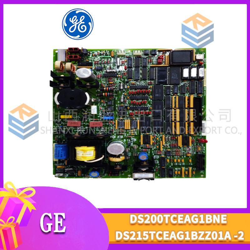
The DS200PTCTG1A is a current transformer termination board for GE’s Mark V DS200 series, used in Speedtronic turbine control systems. It provides a safe, conditioned interface between external current transformers (generator stator currents, line currents) and the Mark V analog input modules.
Unlike generic termination strips, the PTCTG1A includes precision burden resistors, transient suppression, and galvanic isolation for each of the 8 CT channels. This board converts 5 A or 1 AC secondary currents to a low-level voltage signal compatible with standard analog inputs. No external burden resistors to size or install—everything is onboard.
Key Technical Specifications
| Parameter | Value |
|---|---|
| Number of CT inputs | 8 (individually isolated) |
| CT secondary rating | 5 A nominal (1 A optional via jumper) |
| Burden resistor | 0.1Ω ±0.1%, 5 W, wirewound (for 5 A) |
| Output voltage at rated current | 0.5 VAC at 5 A input |
| Overload rating | 20 A continuous, 100 A for 1 second |
| Transient protection | MOV + TVS diode, clamping at ±10 V on output side |
| Isolation voltage | 1500 VAC input-to-output for 1 minute |
| Isolation resistance | >100 MΩ at 500 VDC |
| Frequency range | 45–65 Hz |
| Accuracy | ±0.2% of reading from 0.5 A to 5 A |
| Phase shift | <0.5 degrees at 60 Hz |
| Terminal type | Screw clamp, 12–24 AWG (CT side), cage clamp (output side) |
| Connection to I/O module | 16-pin ribbon cable (included) or individual wire outputs |
| Operating temperature | −30°C to +65°C |
| Storage temperature | −40°C to +85°C |
| Power supply | None (passive) |
| Dimensions | 200 mm x 120 mm x 40 mm |
| Accessories included | Shorting blocks (4), spare burden resistors (2 per channel), labeling strips |
Key Selling Points & Differentiators
- Burden resistors pre-installed and precision-matched – No calculations, no external components. Each channel has a 0.1Ω ±0.1% resistor. Output is 0.5 VAC at 5 A input. Directly compatible with standard analog input modules (0–1 VAC range).
- Dual shorting blocks per channel – Safely short CT secondaries before opening the circuit. We include removable shorting blocks for each pair of channels. Never leave a CT secondary open—dangerous high voltages can develop. The PTCTG1A makes safe work practices easy.
- Optional 1 A secondary configuration – Change jumper position to select 1 A CTs. Burden resistor network reconfigures automatically. Output remains 0.5 VAC at rated current.
- Galvanic isolation protects analog inputs – 1500 VAC isolation between field CT wiring and the Mark V backplane. Prevents ground loops and protects against insulation failures in the CT circuit.
- QC includes burden resistor verification – Every resistor measured for value (0.1Ω ±0.002Ω) and power rating. We also test transient suppression by applying 500 V, 1.2/50 µs surge to each input. Output clamps under ±10 V.
- 2-year warranty – Covers burden resistor failure, isolation breakdown, shorting block damage, or any manufacturing defect.
Frequently Asked Questions (FAQ)
Q: What’s the difference between DS200PTCTG1A and the original PTCTG1 (non-A)?
A: The “A” revision adds two improvements. First: upgraded burden resistors from 3 W to 5 W—original resistors overheated at 5 A continuous in 60°C ambient. Second: redesigned shorting blocks with positive detent (they click into place). The original blocks would vibrate loose in high-vibration turbine applications. We’ve seen that failure mode dozens of times. The A revision solves both.
Q: Can I use this board with 5 A CTs and a 0–1 mA analog input instead of 0–1 V?
A: No. The PTCTG1A outputs voltage (0.5 VAC at 5 A). If your analog input expects 0–1 mA, you’ll need an external current-to-voltage converter or a different termination board. The DS200PTCTx series is voltage output only. Check your I/O module specifications before ordering.
Q: How do I safely short the CTs when removing the board?
A: Use the included shorting blocks. Each block covers two channels. Slide the block into the open position (labeled “SHORT”) before disconnecting any wiring. This shorts the CT secondary through a 0.1Ω path—safe for the CT. After the board is disconnected, you can remove the shorting block if you need to test the CT. Reverse the process when reinstalling. Never rely on the burden resistor alone as a shorting path.
Q: What happens if a CT secondary opens while connected to this board?
A: The burden resistor provides a continuous path—1.0Ω total (0.1Ω resistor plus wiring). So the CT never sees an open circuit while connected. However, if you remove the wiring without shorting first, the CT secondary opens. That generates dangerous high voltage (thousands of volts) and can destroy the CT insulation. Use the shorting blocks. We include a laminated safety card with every board.
Q: Can I use this board for DC current measurement (hall effect sensors, shunts)?
A: No. The PTCTG1A is AC-coupled through the burden resistor network and transient protection. DC current will not produce a usable output. For DC current, use the DS200PTDCG series termination boards. We carry those as well.
Q: What accuracy can I expect at very low currents (under 0.5 A)?
A: At 0.1 A input (2% of rated), accuracy degrades to ±2% due to the burden resistor’s thermal EMF effects and the CT’s own magnetizing current error. For low-current measurements, use a higher-ratio CT (e.g., 5,000:5 instead of 1,000:5) or a separate low-current CT. The PTCTG1A is optimized for 0.5–5 A operation.
Q: The board has 8 inputs. Can I use only 4 and leave the others disconnected?
A: Yes. Unused inputs require no termination. However, we recommend installing the shorting blocks on unused channels in the “SHORT” position to prevent any noise pickup. The shorting block provides a low-impedance path to ground through the burden resistor.
Q: What QC tests do you run on the PTCTG1A?
A: Eight tests:
- Visual: Solder joints, especially on burden resistors (high-heat areas).
- Burden resistance: Each channel measured at 0.1Ω ±0.002Ω.
- Isolation: 1800 VAC for 5 seconds between CT terminals and output. Leakage <0.5 mA.
- Accuracy test: 1 A, 2 A, 3 A, 4 A, 5 A applied to each channel. Output voltage verified within ±0.25%.
- Phase shift: Measured at 60 Hz, 5 A. Must be <0.5 degrees.
- Overload test: 20 A applied for 1 minute. No resistor drift >0.5%. 100 A for 1 second—no physical damage.
- Transient test: 500 V, 1.2/50 µs surge applied to each CT input. Output clamped under ±12 V.
- Shorting block operation: 50 insertion/removal cycles per block. Detent must hold.
Q: What shipping protection?
A: Anti-static bag with conductive foam. The shorting blocks ship installed in the “OFF” (non-shorted) position with protective tape to prevent movement. Accessories (spare resistors, labels) in a separate bag. Box with ESD warning and “FRAGILE” labels. For multiple boards, each PTCTG1A ships individually to protect the shorting blocks from being knocked into the “SHORT” position during transit.


IS200VCRCH1BBC GE
DS215TCDAG1BZZ01A GE
DS215TCQAG1BZZ01A GE
IS220PAICH1A GE
 Email: sales@plcfcs.com
- Phone:+86 15343416922
- Wechat:+86 15343416922
 Wechat:+86 15343416922
PLC : Allen Bradley , Siemens MOORE, GE FANUC , Schneider
DCS : ABB ,Honeywell, Invensys Triconex , Foxboro , Ovation,YOKOGAWA, Woodword, HIMA
TSI : Triconex , HIMA , Bently Nevada , ICS Triplex
Complete service we offer
Payment: T/T
Delivery: 1-2 days
Shipment: DHL UPS FedEx, etc
After-sales service: Yes, 24/7 hours