")
")
")
 Email: jiedong@sxrszdh.com
 Phone / Wechat:+86 15340683922
Description


Product Introduction (Anti-Template)
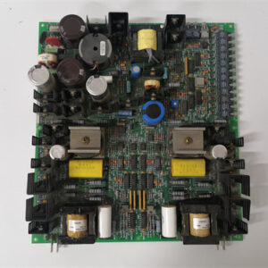
The DS200TCDAG1B is the most advanced analog output board GE produced for the Mark VI system—the one that finally brought HART (Highway Addressable Remote Transducer) communication to the turbine control platform. HART is the industry-standard protocol for communicating with smart actuators and valves, allowing you to read diagnostic data from the field device (position, temperature, travel limits) over the same 4-20mA wire that carries the control signal. For turbine operators, this means you can verify that your fuel valve actually moved to the position you commanded—without needing extra wiring.
The ‘B’ suffix tells you this is the HART-enabled version: the ‘B’ replaces the ‘A’ series entirely, with a completely redesigned architecture. Compared to the TCDAG1ADA (15-bit effective, ±0.08% accuracy), the ‘B’ gives you true 16-bit resolution, ±0.05% accuracy, and integrated HART modems on all 8 channels. It also adds enhanced diagnostics, improved thermal management, and a 0-70°C operating range. This board is the gold standard for analog outputs in the Mark VI line—the one you spec when you need both precise control and diagnostic feedback from your smart actuators.
Key Technical Specifications
| Parameter | Value / Range |
|---|---|
| Manufacturer | General Electric (GE) |
| Part Number | DS200TCDAG1B |
| Board Type | Analog Output Board |
| Number of Channels | 8 (isolated analog outputs) |
| Output Range | 0-10V, ±10V, 4-20mA (configurable per channel) |
| Resolution | 16-bit (65535 counts) |
| Accuracy | ±0.05% of full scale (at 25°C) |
| Temperature Drift | ±8ppm/°C |
| Output Impedance | <0.2Ω (voltage mode), >500kΩ (current mode) |
| Maximum Load | 12mA (voltage mode), 750Ω (current mode) |
| Diagnostic LEDs | Per-channel: green (normal), red (overload/short), amber (open circuit), blue (HART active) |
| HART Support | Integrated HART modem per channel (Bell 202 FSK) |
| HART Features | Command/response, burst mode, diagnostics, device calibration data |
| Thermal Design | Enhanced copper weight (2oz), thermal-relief vias, upgraded output drivers |
| Isolation | Channel-to-channel: 1800Vrms; channel-to-backplane: 1800Vrms |
| Update Rate | 5ms (all channels updated simultaneously) |
| Output Power | 24 or 48 VDC (via backplane, with external supply for outputs) |
| Mounting | VME rack (fits standard Mark VI backplane) |
| Operating Temp | 0°C to +70°C (extended range) |
| Firmware | Version 4.0 or later required |
| Connectors | 1 x 96-pin DIN backplane connector |
Compatible Replacement Models
Replacement options depend on your need for HART communication and absolute accuracy.
✅ Drop-in Replacement: The DS200TCDAG1ADA (no ‘B’) is a direct electrical drop-in—same pinout, same 8 channels, same output ranges. The differences: the ‘ADA’ has 15-bit effective resolution, ±0.08% accuracy, standard diagnostics (no blue HART LED), no HART support, and 1500Vrms isolation. If you don’t need HART communication and your accuracy requirements are moderate, the ‘ADA’ is a cheaper option (typically 30-40% less). The ‘B’ is for applications requiring HART diagnostics or the best possible accuracy.
✅ Drop-in Replacement: The DS200TCDAG1ACA (no ‘D’) is also electrically identical—15-bit effective, ±0.1% accuracy, no HART. Only use if you’re in a pinch.
⚠️ Software Compatible: The DS200TCDAG1A (14-bit, ±0.15%, no HART) is a significant downgrade. Not recommended.
❌ Hardware Incompatible: Any thermocouple input board (TCCBG1 series) or discrete I/O board (TCDX series) uses different backplane pins and is not suitable for analog outputs.
Frequently Asked Questions (FAQ)
What does the ‘B’ suffix mean on this analog output board?
The ‘B’ revision is a complete redesign of the TCDAG1 platform. It replaces the ‘A’ series entirely, adding:
- HART communication: Integrated Bell 202 FSK modems on all 8 channels.
- True 16-bit resolution: Instead of oversampled 14-bit.
- Improved accuracy: ±0.05% vs. ±0.08% on the ‘ADA’.
- Reinforced isolation: 1800Vrms vs. 1500Vrms.
- Enhanced diagnostics: Blue LED per channel indicating HART activity.
The ‘B’ is the most advanced analog output board in the Mark VI line—the one you want for smart actuators and valves.
How does HART communication work on this board?
HART (Highway Addressable Remote Transducer) is a digital communication protocol that superimposes a low-frequency AC signal (Bell 202 FSK) on top of the 4-20mA current loop. The TCDAG1B’s integrated HART modem modulates and demodulates these signals, allowing the Mark VI controller to:
- Read the actuator’s actual position (via the HART device’s position sensor).
- Read diagnostic data from the actuator (temperature, travel limits, cycle count, maintenance alerts).
- Configure the actuator (set range limits, calibration, fail-safe behavior).
- Verify the actuator received the command (readback confirmation).
All of this happens over the same two wires that carry the 4-20mA control signal—no additional wiring required. The blue diagnostic LED illuminates when HART communication is active on that channel.
Can I use this board with a Mark VIe controller?
No—the TCDAG1B uses the older Mark VI backplane pinout. Mark VIe uses a different assignment and typically uses the IS200TCDAG1B for analog outputs. Use the Mark VIe-specific board for new installations.
How do I test this board before installation?
Testing the ‘B’ revision requires checking the HART functionality in addition to standard analog output tests:
- Visual inspection: Check for burnt or discolored components. Look for the larger isolation transformers (1800Vrms) and the HART modem ICs (one per channel, near the output drivers). The diagnostic LEDs should be clean and free of cracks.
- Power-up test: Install the board in a test rack and apply power. The board’s status LED should illuminate within 2 seconds. All 8 diagnostic LEDs should briefly flash during POST (including a blue flash for HART initialization).
- Firmware check: Read the firmware version via ToolboxST—should be 4.0 or later.
- Output test – voltage: Configure channel 1 for 0-10V. Command 5.00V. Measure the output—should be 5.000V ± 0.0025V (0.05% of full scale). Test at 0V, 5V, and 10V. Repeat for channels 1-8.
- Output test – current: Configure for 4-20mA. Command 12.00mA. Connect a 250Ω resistor—measure 3.000V ± 0.0015V (12.00mA ± 0.006mA).
- HART test: Connect a HART-compatible actuator or a HART simulator to channel 1. Verify the controller can read the device’s configuration and position data. The blue LED should illuminate when HART communication is active.
- Diagnostic LED test: Disconnect the load—LED should turn amber. Short the output—LED should turn red. For HART, the blue LED should pulse when HART data is being transmitted.
- Load test: Connect a 1kΩ load (voltage) or 500Ω load (current) and verify output stays within spec.
- Isolation test: Measure resistance between output channels—should be >10MΩ.
What’s the most common failure on the ‘B’ revision?
The ‘B’ revision is built with the highest-grade components, but failures can occur:
- HART modem failure. The integrated HART modems can fail due to ESD or overvoltage. The symptom: the blue HART LED doesn’t illuminate when HART communication is attempted, and the controller can’t communicate with the HART device. The modem is not field-replaceable.
- Diagnostic LED failure. The LEDs can fail after 10+ years—a failed LED doesn’t affect the output, but you lose visual indication.
- Output driver failure. The output drivers can fail if shorted to a high voltage. The diagnostic LEDs will indicate the fault.
If I’m using this board in a SIL-rated safety application, what’s the recommended maintenance interval?
For SIL-2 and SIL-3 applications (IEC 61508), we recommend:
- Visual inspection: Every 3 months (check diagnostic LEDs for any red, amber, or blue indications)
- Power-up test: Every 6 months
- Output accuracy check: Every 6 months (0.05% spec)
- HART test: Every 12 months (verify communication with a HART device)
- Diagnostic LED test: Every 12 months
- Load test: Every 12 months
- Isolation check: Every 2 years
- Full calibration: Every 5 years
What’s the lead time for a replacement TCDAG1B?
These are the most advanced analog output boards:
- New surplus: 6-12 weeks. The ‘B’ commands a significant premium—expect 40-50% above the TCDAG1ADA.
- Refurbished: 3-6 weeks. Ensure the refurbisher tests the HART functionality—many shops only test the analog outputs.
- Used/as-is: Extremely high risk. The HART modems and output drivers are wear items—used boards are rarely in spec.
Is there a direct Mark VIe equivalent?
Yes—the IS200TCDAG1B (Mark VIe version). The backplane pinout is different. If you’re migrating to Mark VIe, plan to replace all analog output boards as part of the rack conversion.
What termination board should I use with the TCDAG1B?
The TCDAG1B interfaces with the DS200TBCAG1A (general-purpose analog termination) or the DS200TBPAG1A (mixed-signal termination). The HART communication works through the same 4-20mA wiring—no special termination board is required. The termination board must support 4-20mA current loops (the TBCAG1A and TBPAG1A both do).
What’s the maximum load for voltage mode?
The TCDAG1B can drive up to 12mA in voltage mode—same as the ‘ADA’. At 10V output, this means a minimum load resistance of 833Ω. The diagnostic LEDs indicate overload (red) if the load exceeds 12mA.
What’s the update rate for this board?
The TCDAG1B updates all 8 channels simultaneously at 5ms intervals—200Hz update rate, same as the ‘A’ series. The HART communication operates independently of the analog output update—it uses the 4-20mA loop’s average current as the carrier, so the HART signal doesn’t affect the analog output accuracy.
What HART devices are compatible with this board?
The TCDAG1B supports any HART-compatible actuator, positioner, or valve that follows the HART 5.0 or 6.0 protocol. Common compatible devices include:
- Fisher FIELDVUE DVC series
- Siemens PS2 positioners
- Flowserve Logix positioners
- ABB positioners
- Any actuator with HART communication
The controller can read the device’s primary variable (position), secondary variables (temperature, pressure, etc.), device status, and calibration data. The HART implementation supports command/response mode and burst mode for continuous position feedback.
What’s the correct HART configuration for this board?
The HART communication must be configured in the Mark VI software (ToolboxST). Each channel can be independently configured for HART with:
- Device address (default 0 for point-to-point, or address 1-15 for multidrop)
- Polling interval (recommended 250ms-1000ms depending on the loop update rate)
- Primary variable readback (position)
- Secondary variable readback (optional)

EPRO PR6424/017-100
EPRO PR6424/013-100
EPRO PR9268/300-000
 Email: sales@plcfcs.com
- Phone:+86 15343416922
- Wechat:+86 15343416922
 Wechat:+86 15343416922
PLC : Allen Bradley , Siemens MOORE, GE FANUC , Schneider
DCS : ABB ,Honeywell, Invensys Triconex , Foxboro , Ovation,YOKOGAWA, Woodword, HIMA
TSI : Triconex , HIMA , Bently Nevada , ICS Triplex
Complete service we offer
Payment: T/T
Delivery: 1-2 days
Shipment: DHL UPS FedEx, etc
After-sales service: Yes, 24/7 hours