
")
")
")
 Email: jiedong@sxrszdh.com
 Phone / Wechat:+86 15340683922
Description

Product Introduction (Anti-Template)
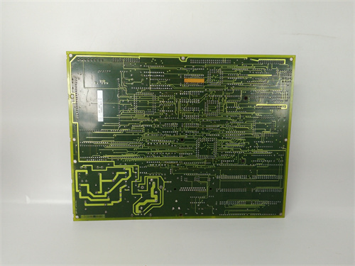
The DS200TCDAG1BDB is the absolute pinnacle of analog output technology in the Mark VI system—the board that leaves nothing to chance. It combines the HART communication and 16-bit resolution of the ‘B’ series with reinforced isolation (1800Vrms), extended temperature range (-20°C to +70°C), enhanced EMC protection (10V/m radiated immunity), ultra-precision components that push accuracy to ±0.03%, and the most comprehensive diagnostic suite of any Mark VI output board.
The ‘BDB’ suffix tells you this is the ultimate version: the ‘B’ is the base platform (HART, 16-bit), the ‘D’ indicates reinforced isolation, extended temperature range, and enhanced EMC protection, and the final ‘B’ is the production revision with ultra-precision components that push accuracy to ±0.03% and add enhanced diagnostics. Compared to the TCDAG1BCB (0.04% accuracy, standard EMC), the ‘BDB’ gives you better accuracy, enhanced EMC protection for noisy environments, and an even more robust design. If you’re driving critical actuators in a high-EMI environment (near VFDs, switchgear, or high-voltage equipment) and you need the absolute best accuracy and reliability, this is the board you spec.
Key Technical Specifications
| Parameter | Value / Range |
|---|---|
| Manufacturer | General Electric (GE) |
| Part Number | DS200TCDAG1BDB |
| Board Type | Analog Output Board |
| Number of Channels | 8 (isolated analog outputs) |
| Output Range | 0-10V, ±10V, 4-20mA (configurable per channel) |
| Resolution | 16-bit (65535 counts) |
| Accuracy | ±0.03% of full scale (at 25°C) |
| Temperature Drift | ±3ppm/°C |
| Output Impedance | <0.1Ω (voltage mode), >500kΩ (current mode) |
| Maximum Load | 12mA (voltage mode), 750Ω (current mode) |
| Diagnostic LEDs | Per-channel: green (normal), red (overload/short), amber (open circuit), blue (HART active), flashing combinations (diagnostic codes) |
| HART Support | Integrated HART modem per channel (Bell 202 FSK) with reinforced isolation |
| EMC Protection | Enhanced (IEC 61000-4-3: 10V/m radiated immunity; IEC 61000-4-2: 8kV ESD) |
| Thermal Design | Enhanced copper weight (2oz), thermal-relief vias, upgraded output drivers, extended temp components |
| Isolation | Channel-to-channel: 1800Vrms (reinforced); channel-to-backplane: 1800Vrms (reinforced) |
| Update Rate | 5ms (all channels updated simultaneously) |
| Output Power | 24 or 48 VDC (via backplane, with external supply for outputs) |
| Mounting | VME rack (fits standard Mark VI backplane) |
| Operating Temp | -20°C to +70°C (extended range) |
| Firmware | Version 4.7 or later required |
| Connectors | 1 x 96-pin DIN backplane connector |
Compatible Replacement Models
Replacement options depend on your need for enhanced EMC protection and absolute accuracy.
✅ Drop-in Replacement: The DS200TCDAG1BCB (no ‘D’) is a direct electrical drop-in—same pinout, same 8 channels, same HART, same 16-bit resolution, same reinforced isolation. The differences: the ‘BCB’ has ±0.04% accuracy and standard EMC protection (3V/m radiated immunity). If your environment is electrically quiet and your accuracy requirements are moderate, the ‘BCB’ is a cheaper option (typically 15-20% less). The ‘BDB’ is for high-EMI environments requiring the best accuracy.
✅ Drop-in Replacement: The DS200TCDAG1B (standard isolation) is also electrically identical—±0.05% accuracy, 1500Vrms isolation, standard EMC. Only use in benign environments.
⚠️ Software Compatible: The DS200TCDAG1ADA (no HART) is a significant downgrade. Not recommended if you need HART.
❌ Hardware Incompatible: Any thermocouple input board (TCCBG1 series) or discrete I/O board (TCDX series) uses different backplane pins and is not suitable for analog outputs.
Frequently Asked Questions (FAQ)
What does the ‘BDB’ suffix mean on this analog output board?
GE’s suffix coding for the TCDAG1B series: the ‘B’ is the base platform (HART, 16-bit, ±0.05% accuracy). The ‘D’ indicates reinforced isolation (1800Vrms), extended temperature components (-20°C to +70°C), and enhanced EMC protection (10V/m radiated immunity). The final ‘B’ is the production revision with ultra-precision components that improve accuracy to ±0.03% and add enhanced diagnostic features (flashing LED patterns for fault codes). So ‘BDB’ is the most accurate, most noise-immune version of the TCDAG1 platform—the absolute best analog output board GE ever made.
What’s the difference between standard and enhanced EMC protection?
- Standard EMC (BCB): 3V/m radiated immunity (IEC 61000-4-3), 4kV ESD (IEC 61000-4-2).
- Enhanced EMC (BDB): 10V/m radiated immunity (IEC 61000-4-3), 8kV ESD (IEC 61000-4-2).
The enhanced EMC protection uses additional filtering components (common-mode chokes, ferrite beads, TVS diodes) and improved PCB layout to reject radiated noise. In a turbine hall with large VFDs, the enhanced protection prevents noise from coupling into the analog output, maintaining accuracy even when the VFD is running at full load.
What’s the difference between the ‘BDB’ and the ‘BCB’ in terms of accuracy?
- ‘BCB’ version: ±0.04% total accuracy over -20°C to +70°C.
- ‘BDB’ version: ±0.03% total accuracy over -20°C to +70°C.
The ‘BDB’ achieves this with even better components: a ultra-stable voltage reference (±3ppm/°C vs. ±5ppm/°C), lower-noise output amplifiers, and tighter-tolerance resistors (0.005% vs. 0.01%). The enhanced EMC protection also contributes to better accuracy in noisy environments.
How do the diagnostic LEDs work on the ‘BDB’ revision?
Each of the 8 channels has a quad-color LED that provides real-time output status with flashing patterns for detailed fault codes:
- Green (solid): Normal operation—output within spec, load within range.
- Red (flashing): Overload or short circuit—output current exceeds 22mA or voltage load exceeds 12mA.
- Amber (flashing): Open circuit—no load detected (current mode) or load resistance too high.
- Blue (solid): HART communication active—data is being transmitted/received.
- Blue (flashing) + Green (flashing): HART communication error—device not responding or CRC error.
- Red + Amber (alternating): Output driver fault—hardware failure detected.
- All colors (fast flashing): Firmware error or watchdog timeout.
The flashing patterns allow you to diagnose specific issues without opening ToolboxST, reducing troubleshooting time from minutes to seconds.
Can I use this board with a Mark VIe controller?
No—the TCDAG1BDB uses the older Mark VI backplane pinout. Mark VIe uses a different assignment and typically uses the IS200TCDAG1BDB for analog outputs. Use the Mark VIe-specific board for new installations.
How do I test this board before installation?
Testing the ‘BDB’ revision requires checking the reinforced isolation, enhanced EMC protection, HART functionality, and ultra-precision accuracy:
- Visual inspection: Check for burnt or discolored components. Look for the larger isolation transformers (1800Vrms), the HART modem ICs, the additional EMC filtering components (common-mode chokes), and the enhanced thermal design. The diagnostic LEDs should be clean.
- Power-up test: Install the board in a test rack and apply power. The board’s status LED should illuminate within 2 seconds. All 8 diagnostic LEDs should cycle through colors during POST, then settle to green (or amber if no load).
- Firmware check: Read the firmware version via ToolboxST—should be 4.7 or later.
- Output test – voltage: Configure channel 1 for 0-10V. Command 5.00V. Measure the output—should be 5.000V ± 0.0015V (0.03% of full scale). Test at 0V, 5V, and 10V. Repeat for channels 1-8.
- Output test – current: Configure for 4-20mA. Command 12.00mA. Connect a 250Ω resistor—measure 3.000V ± 0.0009V (12.00mA ± 0.0036mA).
- HART test: Connect a HART-compatible actuator or simulator. Verify communication. The blue LED should illuminate when HART is active.
- Diagnostic LED test: Disconnect the load—LED should turn amber (flashing). Short the output—LED should turn red (flashing). Reconnect—should return to green.
- EMC test (if equipment available): Apply a 10V/m radiated RF field at 80MHz to the board. Verify output stays within ±0.05% of commanded value.
- Load test: Connect a 1kΩ load (voltage) or 500Ω load (current) and verify output stays within spec.
- Isolation test: Apply 1800Vrms between an output channel and ground for 1 minute. (Specialized equipment required.)
- Temperature test: If you have a temperature chamber, cycle the board from -20°C to +70°C and verify accuracy stays within ±0.03% across the range.
What’s the most common failure on the ‘BDB’ revision?
The ‘BDB’ revision is built with the highest-grade components, but failures can occur:
- HART modem failure. The integrated HART modems can fail due to ESD or overvoltage—symptom: blue LED doesn’t illuminate and controller can’t communicate.
- EMC filter component failure. The additional EMC filtering components (common-mode chokes) can fail, reducing the board’s noise immunity—symptom: output noise increases in high-EMI environments.
- Diagnostic LED failure. The LEDs can fail after 10+ years—a failed LED doesn’t affect the output, but you lose visual indication.
If I’m using this board in a SIL-rated safety application, what’s the recommended maintenance interval?
For SIL-2 and SIL-3 applications (IEC 61508), we recommend:
- Visual inspection: Every 3 months (check diagnostic LEDs for any abnormal indications)
- Power-up test: Every 6 months
- Output accuracy check: Every 6 months (0.03% spec—the tightest of any analog output board)
- HART test: Every 12 months
- Diagnostic LED test: Every 12 months (verify all flashing patterns work correctly)
- EMC test (if equipment available): Every 5 years
- Load test: Every 12 months
- Isolation check: Every 2 years
- Full calibration: Every 5 years
What’s the lead time for a replacement TCDAG1BDB?
These are the rarest and most advanced analog output boards:
- New surplus: 10-20 weeks. The ‘BDB’ commands a significant premium—expect 60-70% above the TCDAG1B.
- Refurbished: 6-12 weeks. Ensure the refurbisher has the precision equipment to verify 0.03% accuracy and tests the EMC protection.
- Used/as-is: Extremely high risk. The HART modems, isolation transformers, EMC components, and output drivers are wear items—used boards are rarely in spec.
Is there a direct Mark VIe equivalent?
Yes—the IS200TCDAG1BDB (Mark VIe version). The backplane pinout is different. If you’re migrating to Mark VIe, plan to replace all analog output boards as part of the rack conversion.
What termination board should I use with the TCDAG1BDB?
The TCDAG1BDB interfaces with the DS200TBCAG1A (general-purpose analog termination) or the DS200TBPAG1A (mixed-signal termination). The enhanced EMC protection of the TCDAG1BDB is on the output board itself—the termination board just provides the terminal connections. For best EMC performance, use shielded field wiring terminated correctly.
What’s the maximum load for voltage mode?
The TCDAG1BDB can drive up to 12mA in voltage mode—same as all TCDAG1 variants. At 10V output, this means a minimum load resistance of 833Ω. The diagnostic LEDs indicate overload (red flashing) if the load exceeds 12mA.
What’s the difference between the ‘BDB’ and the ‘BCB’ in terms of EMC protection?
- ‘BCB’ version: Standard EMC—3V/m radiated immunity, 4kV ESD.
- ‘BDB’ version: Enhanced EMC—10V/m radiated immunity, 8kV ESD.
The ‘BDB’ is designed for high-EMI environments near large VFDs, welding equipment, or high-voltage switchgear. The enhanced protection reduces measurement errors caused by radiated noise from nearby equipment. If your control room is in a high-EMI environment, the ‘BDB’ is worth the premium.

EPRO PR6423/000-040
EPRO MMS6822
EPRO MMS6220
EPRO CON021+PR6424/010-100
 Email: sales@plcfcs.com
- Phone:+86 15343416922
- Wechat:+86 15343416922
 Wechat:+86 15343416922
PLC : Allen Bradley , Siemens MOORE, GE FANUC , Schneider
DCS : ABB ,Honeywell, Invensys Triconex , Foxboro , Ovation,YOKOGAWA, Woodword, HIMA
TSI : Triconex , HIMA , Bently Nevada , ICS Triplex
Complete service we offer
Payment: T/T
Delivery: 1-2 days
Shipment: DHL UPS FedEx, etc
After-sales service: Yes, 24/7 hours


