")
")
")
 Email: jiedong@sxrszdh.com
 Phone / Wechat:+86 15340683922
Description

Product Introduction (Anti-Template)
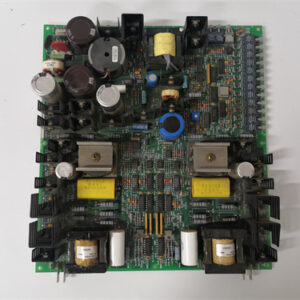
The DS200TBQDG1A takes the 40A brute force of the TBQDG1 and adds the one thing that makes troubleshooting bearable: a green LED per channel that tells you when the output is energized. When you’re dealing with a generator field breaker that pulls 38A and sits behind a locked panel, being able to see the LED from six feet away without opening the cabinet is a gift.
Beyond the LED, this ‘A’ revision improves the thermal design with wider bus bar traces (4oz copper instead of 3oz) and a redesigned ground plane that acts as a heat sink. At 40A full load, the bus bar temperature drops from about 72°C (on the base model) to about 60°C on the ‘A’ version—a 12°C improvement that extends terminal block and solder joint life significantly. Compared to the TBQDG1 (no suffix), the ‘A’ gives you visual output status, runs cooler, and uses a higher-temperature bus bar material (150°C rated vs. 130°C). It’s the board you want if you’re driving a 40A load and you value knowing—at a glance—whether your critical circuit is live.
Key Technical Specifications
| Parameter | Value / Range |
|---|---|
| Manufacturer | General Electric (GE) |
| Part Number | DS200TBQDG1A |
| Board Type | Extreme-High-Current Output Termination Board |
| Number of Channels | 2 (ultra-heavy-duty outputs) |
| Voltage Compatibility | 24, 48, or 125 VDC |
| Current Rating | 40A per channel (continuous) |
| Termination per Channel | 2 independent bus bar terminals (redundant wiring) |
| Status Indication | Green LED per channel (illuminates when energized) |
| Fuse Protection | None (external protection via connected I/O card or upstream panel) |
| Terminal Type | Heavy-duty bus bar clamp (accepts 6-8 AWG) |
| Terminal Pitch | 16mm (maximum spacing for heat dissipation) |
| Bus Bar Material | Tinned copper with 150°C rated insulator |
| Wire Range | 6-10 AWG (8 AWG recommended) |
| Thermal Design | 4oz copper traces; enhanced ground plane heat sinking; thermal-relief vias |
| Solder Alloy | SN96 (high thermal cycling tolerance) |
| Isolation | None (passive; isolation by connected I/O cards) |
| Mounting | VME rack (fits standard Mark VI backplane) |
| Operating Temp | -20°C to +75°C (derate above 50°C) |
| Dimensions | 6U VME form factor |
| Connectors | 2-channel bus bar terminal block (dual terminals per channel); 1 x 96-pin DIN backplane connector (heavy-duty pins) |
Compatible Replacement Models
Replacement options depend on whether you need the status LEDs and improved thermal performance.
✅ Drop-in Replacement: The DS200TBQDG1 (base model) is a direct electrical drop-in—same pinout, same 2 channels, same 40A rating. The differences: no status LEDs, runs about 12°C hotter at full load, uses a lower-temperature bus bar insulator (130°C vs. 150°C). If you don’t need visual status and your rack has good airflow, the base model is a cheaper option, but the ‘A’ version will last longer in hot environments.
⚠️ Software Compatible: The DS200TBQCG1A (4 channels, 20A) fits the rack and is software-compatible, but it cannot handle 40A loads. If your load is under 20A, you could downgrade—but you lose the bus bar terminals and the 40A capacity. Not recommended for applications with current spikes above 20A.
❌ Hardware Incompatible: The DS200TBQBG1A (8 channels, 10A) and DS200TBQAG1A (16 channels, 5A) use different pinouts and are not designed for 40A loads—they’ll fail immediately.
Frequently Asked Questions (FAQ)
What does the ‘A’ suffix add to the TBQDG1?
The ‘A’ revision adds three significant improvements:
- Status LEDs. Each of the 2 channels has a green LED that illuminates when the output is energized. The LED is powered by the output voltage and draws less than 10mA—it doesn’t affect the load current.
- Improved thermal design. The ‘A’ revision uses 4oz copper traces (instead of 3oz on the base model) and a redesigned ground plane that acts as a heat sink. At 40A full load, the bus bar temperature drops from about 72°C to about 60°C at 25°C ambient—a 12°C improvement.
- Higher-temperature bus bar insulator. The ‘A’ version uses a 150°C-rated insulator instead of 130°C on the base model, extending the life of the bus bar assembly in high-temperature environments.
How much heat does this board generate at 40A?
At 40A continuous, the board dissipates about 3-4W per channel in the bus bar contacts and traces, for a total of about 6-8W across both channels. In a 6U VME card with limited airflow, that heat raises the board temperature. The ‘A’ revision’s improved thermal design keeps the bus bar temperature at about 60°C at 25°C ambient (versus 72°C on the base model). At 50°C ambient (common in turbine enclosures), the ‘A’ revision runs at about 85°C—still within spec, but getting close to the limit. If your ambient exceeds 45°C, forced-air cooling is recommended.
How do the status LEDs work on the ‘A’ revision?
Each of the 2 channels has a green LED connected directly across the output terminals (between the ‘A’ and ‘B’ bus bar terminals). When the output is energized (24-125V DC present), the LED illuminates. When the output is de-energized, the LED turns off. The LED is powered by the output voltage itself—no external power source is needed. The LED draws less than 10mA, which is negligible compared to the 40A load current. The LED is visible from a wide angle—you can see it from across a control room. The LED circuit includes a current-limiting resistor sized for operation from 24V to 125V DC, so the LED brightness varies slightly with voltage but is always visible.
Can I use this board with a Mark VIe controller?
No—same platform limitation as all Mark VI boards. The TBQDG1A uses the older Mark VI backplane pinout. Mark VIe uses a different assignment and typically uses the IS200TBQDG1A for this application. The board physically fits but signals map incorrectly—use the Mark VIe-specific board for new installations.
How do I test this board before installation?
Testing a 40A board with status LEDs requires heavy-duty test equipment:
- Visual inspection: Check for burn marks around the bus bar terminals. Inspect the solder joints on the backplane connector—the high-current pins should be bright. The bus bar terminals should be clean and free of corrosion.
- Continuity – primary path: Verify each channel’s “A” bus bar terminal shows <0.05Ω to the backplane pin. Channel 1A to pin A1, up to channel 2A (pin B1).
- Continuity – redundant path: Verify each channel’s “B” bus bar terminal shows <0.05Ω to the same backplane pin.
- Cross-check: Measure resistance between “A” and “B” terminals on the same channel—should be <0.02Ω.
- LED test: Apply 24V DC between the ‘A’ and ‘B’ terminals (or from ‘A’ to ground) of a channel. The green LED should illuminate. Remove voltage; the LED should turn off. Test both channels. At 24V, the LED will be visible; at 125V, it will be brighter.
- Insulation: Measure between adjacent channels—should be >10MΩ.
- Load test: Apply 40A through each channel. Measure voltage drop from terminal to backplane—should be <0.1V at 40A. Monitor the bus bar temperature—at 25°C ambient, it should stabilize below 70°C.
What’s the correct torque for the bus bar terminal screws?
Same as the TBQDG1: 1.8 N·m (about 15.9 in-lb). The M5 bus bar terminal screws require this torque for low contact resistance at 40A. The ‘A’ revision uses the same heavy-duty bus bar assembly. Use a torque screwdriver or torque wrench. At 1.8 N·m, you’ll feel firm resistance. Do not exceed 1.8 N·m.
What’s the most common failure on the ‘A’ revision?
The ‘A’ revision addressed the main failure points of the base model, but two issues remain:
- Bus bar terminal corrosion. The tinned copper bus bars can corrode in humid or chemical environments. The ‘A’ revision’s bus bar material is the same as the base model—corrosion is still a concern. Inspect the bus bars annually; if you see green or white deposits, clean them with a contact cleaner. In coastal plants, quarterly inspections are recommended.
- LED failure. The green LEDs are reliable but can fail over time—a failed LED doesn’t affect the electrical function, but you lose visual feedback. The LED circuit is simple—test it during bench checks.
If I’m using this board in a SIL-rated safety application, what’s the recommended maintenance interval?
For SIL-2 and SIL-3 applications (IEC 61508), we recommend:
- Visual inspection: Every 3 months (check bus bar terminals, look for corrosion, verify LED status)
- Thermal check: Every 3 months (measure bus bar temperature at full load—should be below 70°C at 25°C ambient)
- Torque verification: Every 3 months (re-torque bus bar terminal screws to 1.8 N·m)
- Continuity check: Every 6 months (verify both the ‘A’ and ‘B’ paths)
- Load test: Annually (verify 40A capability and voltage drop within spec)
The ‘A’ revision’s improved thermal design allows you to extend the thermal check to 6 months in cool, clean environments, but the 3-month schedule is still recommended for critical safety circuits.
What’s the lead time for a replacement TBQDG1A?
These are the least common boards in the TBQ series:
- New surplus: 6-12 weeks. The ‘A’ version commands a premium—expect 15-20% above the base model.
- Refurbished: 3-6 weeks. Ensure the refurbisher tests the LEDs and performs a full 40A load test. Some only test continuity and skip the load test.
- Used/as-is: Very high risk. The board’s thermal stress and 40A current mean used boards often have degraded bus bar terminals. The ‘A’ revision’s improved thermal design makes used boards more reliable than the base model, but inspect carefully.
Is there a direct Mark VIe equivalent?
Yes—the IS200TBQDG1A (Mark VIe version). But the backplane pinout is different, and the Mark VIe board may have different LED colors or diagnostics. If you’re migrating to Mark VIe, plan to replace all extreme-high-current boards as part of the rack conversion.
Can I use this board with 125V DC at 40A?
Yes—the TBQDG1A is rated for 125V DC at 40A continuous. The LED will be bright at 125V—visible from across the rack. At these levels:
- You must use 6 AWG wire to minimize IR heating
- The rack should have forced-air cooling
- The bus bar terminal screws must be torqued to 1.8 N·m
- Keep the bus bars clean—any contamination can cause arc-tracking at 125V
We’ve used these boards at 125V DC / 40A in large gas turbine generator applications without issues. The ‘A’ revision’s improved thermal design makes them more reliable than the base model at these levels. Regular thermal monitoring (every 3 months) is essential—if you see a bus bar exceeding 80°C, investigate immediately.
What’s the difference between the TBQDG1A and the TBQDG1 in terms of bus bar material?
The base TBQDG1 uses a standard bus bar insulator rated for 130°C. The TBQDG1A uses a higher-temperature UL 94V-0-rated material rated for 150°C. The difference in bus bar copper is also significant—the ‘A’ uses 4oz copper traces versus 3oz on the base model. The ‘A’ version will last about 30-40% longer in high-temperature environments, making it the better choice for hot turbine decks.

GILBARCO T17299-G1 PLC DCS
GILBARCO Q13086-02R PLC DCS
CB06251 PLC DCS
 Email: sales@plcfcs.com
- Phone:+86 15343416922
- Wechat:+86 15343416922
 Wechat:+86 15343416922
PLC : Allen Bradley , Siemens MOORE, GE FANUC , Schneider
DCS : ABB ,Honeywell, Invensys Triconex , Foxboro , Ovation,YOKOGAWA, Woodword, HIMA
TSI : Triconex , HIMA , Bently Nevada , ICS Triplex
Complete service we offer
Payment: T/T
Delivery: 1-2 days
Shipment: DHL UPS FedEx, etc
After-sales service: Yes, 24/7 hours