")
")
")
 Email: jiedong@sxrszdh.com
 Phone / Wechat:+86 15340683922
Description

Product Core Brief
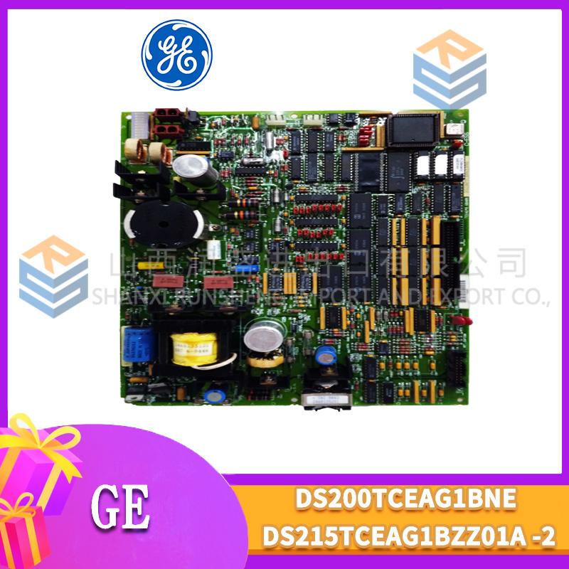
- Model: DS200RTBAG2AHC
- Brand: General Electric (GE)
- Series: Mark V DS200
- Core Function: Hybrid relay board with mechanical and solid state outputs
- Product Type: Hybrid Relay Output Board (32 channels)
- Key Specs: 16 mechanical (10 A) + 16 SSR (2 A fast) | 2 isolated banks | Mixed technology
- Condition: New Original.
Product Introduction
The DS200RTBAG2AHC is a hybrid relay output termination board for GE’s Mark V DS200 series, used in Speedtronic turbine control systems. It provides 32 outputs across two banks: Bank A has 16 mechanical relays (10 A, Form C, high current) and Bank B has 16 solid state relays (2 A, <100 µs switching, silent operation).
The “2AHC” suffix indicates a hybrid configuration—the only RTBA variant that combines both technologies on a single board. This is designed for applications requiring both high-current switching (motor starters, pumps, heaters) and high-speed or silent switching (PWM control, fast valves, indicator panels) without using two separate boards and two rack slots. Bank A handles heavy loads; Bank B handles fast or noise-sensitive loads.
Key Technical Specifications
| Parameter | Bank A (Mechanical) | Bank B (Solid State) |
|---|---|---|
| Number of outputs | 16 (relays 1–16) | 16 (channels 17–32) |
| Output type | Electromechanical, Form C (SPDT) | Solid State, Form A (SPST-NO) |
| Contact rating (resistive) | 10 A @ 250 VAC, 10 A @ 30 VDC | 2 A @ 280 VAC / 60 VDC |
| Contact rating (inductive) | 5 A @ 250 VAC, 5 A @ 30 VDC | 1 A @ 250 VAC (cosφ=0.4) |
| Switching time | 15 ms typical | <100 µs (DC), <8.3 ms + zero-crossing (AC) |
| Maximum switching frequency | 10 Hz | 1 kHz (DC), 120 Hz (AC) |
| Mechanical/Electrical life | 10M / 50k cycles at 10 A | Unlimited / 100M cycles |
| Minimum load | 100 mA @ 12 VDC | None (leakage current applies) |
| Off-state leakage | N/A (mechanical open) | <1 mA AC, <0.1 mA DC |
| Terminal type | Fixed screw, 10–18 AWG | Removable pluggable, 12–24 AWG |
| Per-channel indication | Red + Green LED (contact sense) | Green LED (input signal) |
Shared Parameters (Both Banks)
| Parameter | Value |
|---|---|
| Coil/input voltage | 24 VDC nominal |
| Input current per channel | 30 mA (mechanical), 5 mA (SSR) |
| Total backplane current (all on) | 560 mA max (480 mA mechanical + 80 mA SSR) |
| External coil power option | Bank A only (mechanical relays require 480 mA; SSR bank runs from backplane) |
| Coil suppression (Bank A) | RCD snubber (diode + 470 nF + 47Ω) |
| Protection (Bank B) | Snubber (AC) or TVS (DC) per channel |
| Bank-to-bank isolation | 2500 VAC for 1 minute |
| Operating temperature | −30°C to +60°C |
| Dimensions | 380 mm x 220 mm x 60 mm |
| Weight | 2.8 kg (6.2 lbs) |
| Accessories included | External coil power jumper (Bank A), spare terminal blocks (Bank B, 2 sets), spare relay (Bank A, 1), thermal pad kit, labeling strips, application note: hybrid configuration |
Key Selling Points & Differentiators
- Two technologies, one board, one slot – Mechanical relays for high-current loads (10 A), SSRs for high-speed or silent switching. No need for two separate boards and two rack slots. Reduces cabinet space by 50% compared to using separate RTBA boards.
- Bank A: 16 mechanical relays (10 A, Form C) – Switch motor starters (1 HP at 120 VAC), large solenoids, pump contactors, heater contactors. Bifurcated silver-tin oxide contacts. Fixed screw terminals rated for 10 AWG. Includes per-channel green LED for contact closure verification.
- Bank B: 16 solid state relays (2 A, <100 µs) – PWM control of heaters, high-speed valve arrays, lamp testing, silent switching. Zero-crossing AC or random-turn-on DC (field selectable per channel group). Removable terminal blocks. Unlimited mechanical life.
- Per-bank isolation at 2500 VAC – Bank A (mechanical) and Bank B (SSR) are electrically isolated. Connect Bank A to 240 VAC motor starters and Bank B to 24 VDC fast valves on the same board. No ground loops.
- External coil power option for Bank A only – Mechanical bank draws 480 mA when all relays energized (30 mA x 16). If backplane 24 VDC is limited, move a jumper to power Bank A coils from an external 24 VDC supply (5 A minimum). Bank B (SSR) draws only 80 mA and stays on backplane power.
- Mixed terminal types optimized for each technology – Bank A: fixed screw terminals (10–18 AWG) for high current. Bank B: removable pluggable terminal blocks (12–24 AWG) for easy rewiring of fast-switching loads.
- QC includes separate load tests per bank – Bank A: 10 A resistive on all 16 relays for 24 hours. Bank B: 1 kHz cycling on all 16 SSRs for 1,000 seconds (1,000,000 cycles). Bank-to-bank isolation verified at 3000 VAC.
- 2-year warranty – Covers both banks: mechanical relay contact welding, SSR output failure, coil circuits, or any manufacturing defect.
Frequently Asked Questions (FAQ)
Q: Why would I choose the hybrid RTBAG2AHC instead of separate mechanical and SSR boards?
| Scenario | Separate Boards | Hybrid (2AHC) |
|---|---|---|
| Rack slots needed | 2 slots | 1 slot |
| Cabinet space | Two boards | One board |
| Wiring complexity | Two sets of field wires | One set (but segregated banks) |
| Backplane current | Up to 1.04 A (480 mA + 560 mA) | 560 mA (480 mA + 80 mA) |
| Cost | Higher (two boards) | Lower (one board) |
The hybrid board saves rack space, reduces backplane load, and lowers cost. Choose hybrid when you need both high-current and high-speed outputs in the same application.
Q: Can I replace an existing RTBAG2A (all mechanical) with the 2AHC without changing my Mark V configuration?
A: Partially. The pinout is identical for relays 1–16 (Bank A mechanical). Channels 17–32 on the original RTBAG2A were mechanical relays (Form C). On the 2AHC, channels 17–32 are SSRs (Form A, SPST-NO, 2 terminals instead of 3). If your application uses the NC contact on any of channels 17–32, the 2AHC will not work. If your application uses only the NO contact and load current is under 2 A, you can replace directly. Rewiring required: SSRs have 2 terminals (Line, Load) versus 3 terminals (C, NO, NC) on mechanical.
Q: Can Bank A (mechanical) and Bank B (SSR) operate at different voltages?
A: Yes—that’s the purpose of bank isolation. Bank A (mechanical) can switch 240 VAC motor starters while Bank B (SSR) switches 24 VDC fast valves. The coils/inputs (24 VDC) are common across both banks, but the contact circuits are isolated at 2500 VAC. Do NOT mix voltage types within the same bank (e.g., relay 1 at 240 VAC and relay 2 at 24 VDC in Bank A). They share a common isolation barrier per bank.
Q: How do I configure Bank B (SSR) for AC or DC?
A: Bank B has four groups of 4 channels (channels 17–20, 21–24, 25–28, 29–32). Each group has a 2-position jumper. For AC (zero-crossing), install the jumper. For DC (random turn-on), remove the jumper. Default configuration from the factory: Groups 1 and 2 = AC, Groups 3 and 4 = DC. Change jumpers before installing the board. Do not change with power applied.
Q: The mechanical bank (Bank A) has external coil power option. How do I wire it?
A: Bank A has a 2-position terminal block labeled “EXT 24V+” and “EXT 24V-“. Remove the jumper shunt from the backplane power header (located near the terminal block). Connect an external 24 VDC supply (5 A minimum) to the terminals. The Mark V output module still provides the control signal (opto-isolated). The external supply powers only the mechanical relay coils. Bank B (SSR) remains on backplane power (draws only 80 mA).
Q: What is the maximum switching frequency for Bank B (SSR) with AC loads?
A: 120 Hz maximum (limited by zero-crossing delay). At 60 Hz, a zero-crossing SSR turns on at the next AC zero crossing after the control signal goes high—delay up to 8.3 ms. For PWM applications above 10 Hz, the load will see on/off patterns but the effective power is proportional to duty cycle. For true high-frequency switching (>100 Hz), use DC mode (remove jumpers) and a DC load. We have tested Bank B at 1 kHz DC switching with resistive loads.
Q: The board has two different terminal types. Can I replace a damaged Bank B terminal block?
A: Yes. Bank B uses removable pluggable terminal blocks (2 terminals per channel, 32 total). Spare blocks are included. To replace, squeeze the latches and pull straight up. Bank A uses fixed screw terminals (3 terminals per relay, 48 total). If a Bank A terminal is damaged (bent, stripped), return the board for repair ($45 + return shipping). We do not recommend field repair of Bank A fixed terminals.
Q: What are the thermal limitations for each bank?
A: Bank A (mechanical): 10 A on all 16 relays simultaneously requires panel mounting (thermal pad to metal surface) and forced air cooling (200 LFM minimum). Without forced air, limit to 5 A per relay average. Bank B (SSR): 2 A on all 16 channels simultaneously (32 A total) is not possible—thermal limit is 16 A total per bank (1 A average per channel) with panel mounting. Derating chart included.
Q: What QC tests are specific to the hybrid 2AHC revision?
A: Fourteen tests, separated by bank:
Bank A (Mechanical):
- Coil resistance: 800Ω ±3% (30 mA).
- Contact resistance (NO/NC): <30 mΩ at 1 A, four-wire.
- Load test: 10 A resistive, 24 hours, all 16 relays. Contact resistance <100 mΩ final.
- External coil power test: Verify jumper operation, external supply powers coils.
Bank B (SSR):
- Input current: 5 mA ±1 mA per channel.
- Turn-on/off time (DC mode, sample): <100 µs. Oscilloscope capture.
- On-state voltage drop (sample): <1.5 VAC at 2 A, <1.0 VDC at 2 A.
- Off-state leakage (sample): <1 mA AC, <0.1 mA DC.
- High-cycle test: All 16 channels at 1 kHz (DC mode) for 1,000 seconds (1,000,000 cycles).
Both Banks:
- Bank-to-bank isolation: 3000 VAC for 5 seconds. Leakage <0.5 mA.
- Input-to-output isolation per bank: Bank A: 3000 VAC; Bank B: 5000 VAC.
- Operate test (Bank A) / switching test (Bank B): 500 cycles each.
- Thermal imaging: Full rated load per bank for 2 hours with panel mounting. Hot spots <85°C.
- LED test: Bank A: red+green; Bank B: green.
Q: What shipping protection for this heavy hybrid board?
A: The 2AHC weighs 2.8 kg (6.2 lbs). Anti-static bag, custom ESD foam cradle with separate cutouts for Bank A fixed terminals (48 positions) and Bank B removable blocks (32 positions). Bank B removable blocks shipped installed to protect pin headers. Thermal pad kit (required for loads >5 A on Bank A or >0.5 A average on Bank B) in separate sealed bag. Double-wall box with “HEAVY,” “FRAGILE,” “ESD SENSITIVE,” “DO NOT STACK” labels. Shock indicator on outside. Each board ships individually. Application note on hybrid configuration (12 pages) included as printed document.

CSB01.1N-AN-ENS-NNN-NN-S-NN-FW PLC DCS
HDS03.2-W075N-HS12-01-FW
DKC03.3-040-7-FW PLC DCS
 Email: sales@plcfcs.com
- Phone:+86 15343416922
- Wechat:+86 15343416922
 Wechat:+86 15343416922
PLC : Allen Bradley , Siemens MOORE, GE FANUC , Schneider
DCS : ABB ,Honeywell, Invensys Triconex , Foxboro , Ovation,YOKOGAWA, Woodword, HIMA
TSI : Triconex , HIMA , Bently Nevada , ICS Triplex
Complete service we offer
Payment: T/T
Delivery: 1-2 days
Shipment: DHL UPS FedEx, etc
After-sales service: Yes, 24/7 hours