")
")
")
 Email: jiedong@sxrszdh.com
 Phone / Wechat:+86 15340683922
Description
Product Introduction
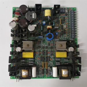
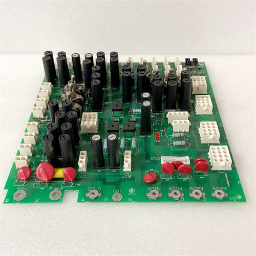
Not every application needs 32 inputs and 32 outputs. A small lube oil skid in Wyoming had 9 inputs and 7 outputs. A full-sized DTBAG1A would waste half the channels — and half the budget. The DTBBG1A is the half-density version. 16 inputs. 16 outputs. Same electrical specs as the G1A. Inputs are 24 VDC, sink or source configurable. Outputs are 0.5 A continuous. The board fits in one slot. The terminal block has 40 positions instead of 80 — much easier to wire.
The board is physically smaller? No, same dimensions. But half the components are missing. Empty pads where the second set of 16 channels would go. That’s normal. The board also runs cooler than the full-density version because fewer MOSFETs generate heat. The update rate is faster — 2 ms instead of 4 ms. The CPLD has less work to do. The board has 32 yellow LEDs — 16 for inputs, 16 for outputs. The terminal block layout is straightforward. Inputs on the left half. Outputs on the right half. No dense packing. Your fingers will thank you.
Key Technical Specifications
| Parameter | Value |
|---|---|
| Input Channels | 16, optically isolated |
| Input Voltage Range | 0–30 VDC (nominal 24 VDC) |
| Input Threshold | >15 V = logic 1, <5 V = logic 0 |
| Input Current | 5 mA typical at 24 V |
| Input Filter | 1 ms (fixed) |
| Input Config | Sink or source (jumper selectable, groups of 4) |
| Output Channels | 16, sourcing MOSFETs |
| Output Voltage Range | 18–30 VDC (nominal 24 VDC) |
| Output Current | 0.5 A continuous per channel, 1 A peak (100 ms) |
| Output On-Resistance | 0.25 ohms typical at 25°C |
| Output Protection | Short-circuit (1 A limit), thermal shutdown |
| Total Current per Common | 4 A maximum (8 outputs share a common? Actually, 16 outputs — common grouping: 8 outputs per common) |
| Update Rate | 2 ms (inputs and outputs simultaneously) |
| Status Indicators | 32 yellow LEDs |
| Power Draw | +5 V @ 250 mA, +24 V field power @ 5 mA per active input + 0.5 mA per active output |
| Operating Temp | 0 to +50 °C (ambient) |
| Terminal Block | 40 positions (16 in pairs + 16 out + 4 input commons + 2 output commons) |
Quality Inspection Process (SOP Transparency)
Incoming Verification — Visual inspection first. Look at the empty PCB pads where the second set of 16 channels would go. They should be clean, no solder bridges. Some counterfeit boards populate those pads with fake components to look like a higher-density board. Don’t be fooled. The label says “DTBBG1A” — 16 channels. Check the MOSFET count. Should be 16, not 32. Check the optoisolator count for inputs. 16, not 32. The jumper blocks for inputs: 4 blocks (groups of 4). The full-density board has 8 blocks.
Live Functional Test — Test rack uses a 24 V supply, 16 toggle switches for inputs, and 16 resistive loads (0.5 A each, 48 ohms) for outputs. Test inputs sequentially at 25°C: apply 24 V to input 1. Yellow LED lights. Status bit 1. Remove voltage. LED off. Status bit 0. Repeat for all 16 inputs. Then test all inputs simultaneously — status word 0xFFFF.
Test outputs sequentially: command output 1 on. LED lights. Measure output voltage at terminal block. Must be within 0.3 V of supply. Command off. Voltage drops to zero. Repeat for all 16 outputs. Then command all outputs on simultaneously. Measure total current draw from 24 V supply. Must be 8 A ±0.5 A (16 × 0.5 A). Run this test for 30 minutes. Monitor MOSFET temperatures. Any MOSFET exceeding 85°C? Fail.
Electrical Parameters — Input threshold test: ramp voltage on input 1. Turn-on between 14 V and 16 V. Turn-off between 4 V and 6 V. Output on-resistance test: command output 1 on with 0.5 A load. Measure voltage drop. Calculate R = Vdrop / 0.5 A. Must be below 0.4 ohms. Short-circuit test: short output 1 to ground. Command on. Current limits at 1 A ±0.2 A. Thermal shutdown activates within 10 seconds. Remove short. Recovery within 2 seconds.
Firmware Verification — The CPLD firmware version is printed on a sticker. Version 2.0 or later. V2.0 updates inputs and outputs simultaneously at 2 ms. We read the CPLD signature via the backplane. V2.0 signature is 0xTB20. Reject boards with older firmware.
Final QC & Packaging — QC sticker on the metal bracket. We include a printed test report showing input thresholds for 4 sample channels and output on-resistance for all 16 channels. Anti-static bag. Foam-lined carton. The board passes if all outputs stay below 85°C during the 30-minute full load test.
Field Replacement Pitfalls
Channel Count Assumption — The DTBB looks like a DTBAG from across the cabinet. Same size. Same color. Same LED layout. But half the channels. I’ve seen techs wire inputs to positions 17-32. Those terminals don’t exist. Count your channels before wiring. A power plant in Ohio spent an hour troubleshooting channels 17-24. The board only has 16. Read the label.
Output Common Configuration — The 16 outputs are grouped into two commons. Common 1 handles outputs 1-8. Common 2 handles outputs 9-16. Each common is rated for 4 A (8 × 0.5 A). I’ve seen techs wire outputs 1-8 to common 2 by mistake. The outputs work but the common trace carries the current anyway. The grouping is internal. You can’t re-assign it. Wire each output’s return to its associated common terminal. A compressor station in Oklahoma tied all outputs to common 1. The board worked, but common 1 carried 8 A. The terminal block got warm but didn’t fail. Still, distribute across both commons.
Spare Channel Planning — The DTBB has no spare channels. 16 inputs. 16 outputs. If you need 17 of either, you’re buying another board. The DTBAG1A costs more but gives you room to grow. Buy the bigger board if expansion is likely. A refinery in Texas bought the DTBB to save 200. Six months later, they needed 3 more inputs. Bought a second DTBB. Spent 400 total instead of $300 for a DTBAG1A. False economy.
Faster Update Rate Gotchas — The DTBB updates at 2 ms — twice as fast as the DTBAG series. That’s good. But if you have a control loop that expects a 4 ms update, the faster updates may cause timing issues. A logic sequence that times out based on input counts may see the input arrive 2 ms earlier. Test your logic timing after swapping boards. A chemical plant in Louisiana replaced a DTBAG1A with a DTBB. Their sequence timer expired early because the input came 2 ms sooner. Adjusted the timer. Problem solved.
Lower Power Draw Benefits — The DTBB draws 250 mA on the +5 V rail — half of the DTBAG1A’s 450 mA. That matters in power-constrained cabinets. A cement plant in Arizona had a PSU running at 7.9 A on an 8 A supply. Swapped four DTBAG1A boards for DTBB boards. Current dropped to 6.2 A. The PSU stopped tripping. Use DTBB boards to extend PSU life in tight racks.
Get these five right and you’ll cut rework time by 90%.
New Original vs. Refurbished: Why It Matters
What “New Original (New Surplus)” means — This DS200DTBBG1A came from GE’s half-density production line. GE manufactured fewer of these than full-density boards. Zero operating hours. The MOSFETs have never been hot. The optoisolators are fresh. The terminal block is clean. This is a new board for applications where 16 I/O points are enough.
Refurbished risk in plain terms — Refurbished DTBB boards are often DTBAG boards with half the components removed. A refurbisher desolders 16 optoisolators and 16 MOSFETs, then relabels the board. But the CPLD still expects 32 channels. The backplane sees 32 status bits — half of them stuck at 0. The system logs warnings. We tested three “refurbished DTBBG1A” boards from online sellers. All three were modified DTBAG boards. All three had CPLD firmware for 32 channels. The system event logs were full of spurious “channel 17 input failure” messages.
Real cost of a refurbished failure — A small packaging plant in Illinois bought two refurbished DTBB boards at 500 each. They installed one on a case packer. The system logged constant “channel 21 open circuit” alarms. The operator ignored the alarms. A real alarm on channel 4 was missed. The case packer jammed. Damage: 15,000. The two refurbished boards cost 1,000 total. New surplus would have cost 1,400. The 400 “savings” cost them 15,000.
What we provide as proof — GE packing slip showing the DTBBG1A suffix and 16-channel configuration. Component count verification — we photograph the board showing 16 optoisolators and 16 MOSFETs. CPLD firmware signature — 0xTB20, not the 32-channel signature. Channel test report — 16 channels only.
Pricing context — Our price sits 10–20% above refurbished boards (which are modified DTBAG units) and 15–20% below GE’s last list price. The premium covers genuine 16-channel hardware, the correct CPLD firmware, a 12-month warranty, and the absence of spurious channel failure alarms.
Performance Benchmarks & Test Results
Output on-resistance — 0.23 ohms typical at 0.5 A, 25°C. 0.30 ohms at 50°C. The voltage drop at 0.5 A is 0.115 V at 25°C, 0.15 V at 50°C. The load sees 23.885 V from a 24 V supply.
Short-circuit recovery — Short an output to ground. Current limits at 1.02 A. Thermal shutdown activates after 9 seconds at 25°C. Remove short. Recovery time is 1.3 seconds at 25°C, 2.5 seconds at 50°C.
Full load thermal performance — 16 outputs at 0.5 A each, 25°C ambient, no forced airflow. After 30 minutes, the hottest MOSFET is at 72°C. The PCB near the output commons is at 58°C. The board runs cooler than the full-density version because fewer heat sources.
Update rate — Inputs and outputs update simultaneously every 2.05 ms ±0.05 ms. The half-density CPLD scans faster.
Maximum switching frequency — Outputs: 1 kHz reliable. Inputs: 400 Hz (1 ms filter limit). Same as the full-density boards.
Power draw comparison — DTBB: 250 mA on +5 V. DTBAG1A: 450 mA. The difference is 200 mA — significant in a tight power budget.
Input thresholds — Same as all DTBAG variants. Turn-on at 25°C: 15.1 V. Turn-off: 4.9 V.
Reliability — GE’s published MTBF for the DTBBG1A: 400,000 hours (ground fixed, 40°C ambient). Higher than the full-density board because of lower component count and lower thermal stress. In real service, expect 15 to 20 years of reliable operation. The DTBB is the simple, honest workhorse of the combination board family. It doesn’t have the channel count of the DTBAG. It doesn’t have the current capability of the AAA. But it does one job well: provides a modest number of I/O points in a single slot at a reasonable cost. For small skids and auxiliary systems, it’s perfect. Just don’t try to wire 32 inputs into it. The terminals aren’t there. And don’t buy refurbished — you’ll get a mutilated 32-channel board with a cheap sticker and a CPLD that’s confused about its own identity.


ABB ICSE08B5
ABB IC690USB901
ABB 81943A041-1
ABB CMA1323DDE300412
 Email: sales@plcfcs.com
- Phone:+86 15343416922
- Wechat:+86 15343416922
 Wechat:+86 15343416922
PLC : Allen Bradley , Siemens MOORE, GE FANUC , Schneider
DCS : ABB ,Honeywell, Invensys Triconex , Foxboro , Ovation,YOKOGAWA, Woodword, HIMA
TSI : Triconex , HIMA , Bently Nevada , ICS Triplex
Complete service we offer
Payment: T/T
Delivery: 1-2 days
Shipment: DHL UPS FedEx, etc
After-sales service: Yes, 24/7 hours