")
")
")
 Email: jiedong@sxrszdh.com
 Phone / Wechat:+86 15340683922
Description

Product Introduction (Anti-Template)
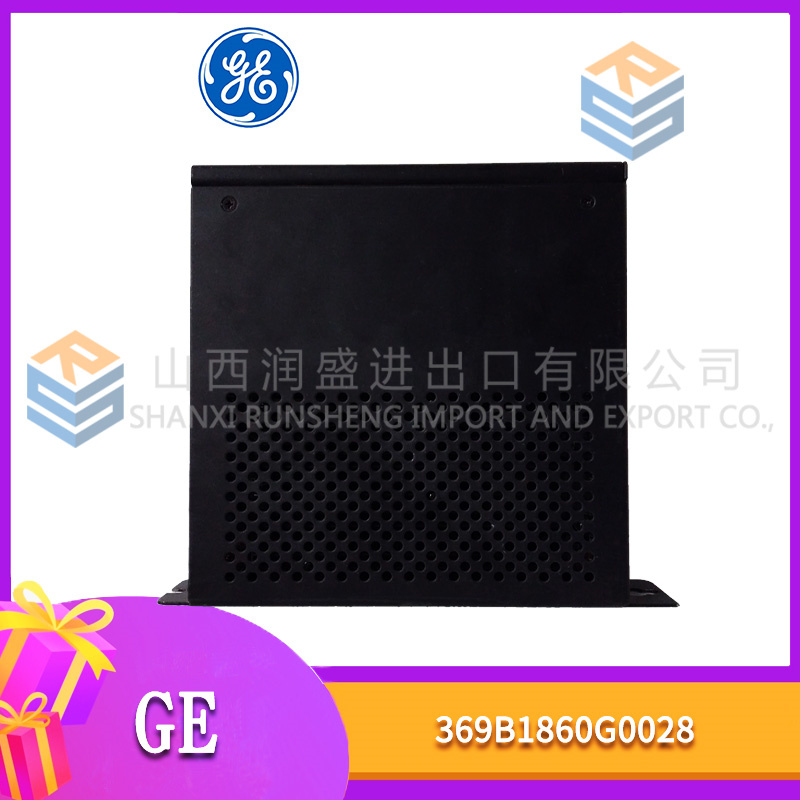
The DS200TCQFG1B is the absolute best discrete input board GE produced for the Mark VI system—the board that combines 8 discrete inputs with configurable thresholds, reinforced isolation (1800Vrms), galvanic isolation, extended temperature operation (-20°C to +70°C), enhanced EMC protection (10V/m radiated immunity), advanced diagnostics, and advanced time-stamping (±50µs accuracy) for the most demanding turbine control applications.
The ‘TCQF’ in the part number indicates this is a discrete input board with configurable thresholds. The ‘B’ suffix tells you this is the ultimate version: reinforced isolation (1800Vrms), galvanic isolation, extended temperature range (-20°C to +70°C), enhanced EMC protection, 5ms update rate, diagnostic LEDs per channel, configurable input thresholds, advanced diagnostics, and advanced time-stamping with ±50µs accuracy. Compared to the TCQFG1ACC (±100µs time-stamping), the ‘B’ gives you double the time-stamping accuracy. This is the board you spec when you need the absolute best performance from your discrete inputs.
Key Technical Specifications
| Parameter | Value / Range |
|---|---|
| Manufacturer | General Electric (GE) |
| Part Number | DS200TCQFG1B |
| Board Type | Discrete Input Board |
| Number of Channels | 8 (isolated discrete inputs) |
| Input Voltage | 24, 48, or 125 VDC (configurable per input) |
| Threshold Configurability | Software-adjustable per channel |
| Input Type | Wet/dry contacts (sourcing or sinking) |
| Update Rate | 5ms (all channels updated simultaneously) |
| Time-Stamping | Advanced input state change time-stamping (±50µs accuracy) |
| Galvanic Isolation | Separate isolated power supply and signal path for each input channel |
| Enhanced Diagnostics | Input threshold detection, cable open detection, input voltage level reporting, noise immunity monitoring, input impedance measurement, hysteresis monitoring |
| Diagnostic LEDs | Per-channel: green (ON), amber (OFF), red (fault), white (time-stamping active), blue (galvanic isolation active), flashing combinations for diagnostic codes |
| Isolation | Channel-to-channel: 1800Vrms (reinforced); channel-to-backplane: 1800Vrms (reinforced); galvanic isolation (input-to-backplane) |
| EMC Protection | Enhanced (IEC 61000-4-3: 10V/m radiated immunity; IEC 61000-4-2: 8kV ESD; IEC 61000-4-5: 2kV surge) |
| Input Power | 24 or 48 VDC (via backplane) |
| Mounting | VME rack (fits standard Mark VI backplane) |
| Operating Temp | -20°C to +70°C (extended range) |
| Firmware | Version 5.5 or later required |
| Connectors | 1 x 96-pin DIN backplane connector |
Compatible Replacement Models
Replacement options depend on your need for the highest time-stamping accuracy and the most comprehensive diagnostics.
✅ Drop-in Replacement: The DS200TCQFG1ACC (±100µs time-stamping) is a direct electrical drop-in—same pinout, same 8 inputs, same voltage ranges, same configurable thresholds, same update rate, same isolation. The differences: the ‘ACC’ has ±100µs time-stamping accuracy. If you don’t need ±50µs accuracy, the ‘ACC’ is a cheaper option (typically 10-15% less). The ‘B’ is for applications requiring the highest time-stamping accuracy.
✅ Drop-in Replacement: The DS200TCQFG1ACB (no galvanic isolation, no time-stamping) is a significant downgrade—only use if you’re in a pinch.
⚠️ Software Compatible: The DS200TCQAF1B (16 inputs, 5ms update) provides more channels but with fixed thresholds. Only use if you need 16 inputs and don’t need configurable thresholds.
⚠️ Software Compatible: The DS200TCQCG1A (8 relay outputs) provides outputs only—not suitable for inputs.
❌ Hardware Incompatible: Any analog input board (TCCAG1 series) uses different backplane pins and is not suitable for discrete signals.
Frequently Asked Questions (FAQ)
What does the ‘B’ suffix mean on this discrete input board?
The ‘B’ revision is a major upgrade over the ‘ACC’ version. It adds:
- ±50µs time-stamping accuracy (vs. ±100µs on ‘ACC’)
- Enhanced diagnostics: Hysteresis monitoring, improved input impedance measurement
- Reinforced isolation: 1800Vrms
- Galvanic isolation: Separate isolated power supply and signal path for each input channel
- Extended temperature range: -20°C to +70°C
- Enhanced EMC protection: 10V/m radiated immunity, 8kV ESD, 2kV surge
What’s the difference between ±50µs and ±100µs time-stamping?
The ±50µs accuracy (on the ‘B’) is twice as accurate as the ±100µs accuracy (on the ‘ACC’). For applications requiring precise event correlation—such as sequencing logic, safety interlocks, or post-event analysis—the ±50µs accuracy provides better resolution and more precise timing data. The improved accuracy is achieved with a higher-precision timestamping circuit and better synchronization with the Mark VI system clock.
How does hysteresis monitoring work on the ‘B’?
The ‘B’ monitors the input’s hysteresis—the difference between the ON and OFF thresholds. For a typical digital input, there’s a small hysteresis (the input turns ON at 14V and OFF at 12V). If the hysteresis becomes too small, the input may chatter (rapidly oscillate) in noisy environments. The ‘B’ reports the hysteresis value for each channel in ToolboxST and generates an alert if the hysteresis falls below a configurable threshold, allowing you to detect input circuit degradation before it causes problems.
Can I use this board with a Mark VIe controller?
No—the TCQFG1B uses the older Mark VI backplane pinout. Mark VIe uses a different assignment and typically uses the IS200TCQFG1B for discrete inputs. Use the Mark VIe-specific board for new installations.
How do I test this board before installation?
Testing the TCQFG1B requires checking all 8 inputs with different threshold settings, verifying galvanic isolation, reinforced isolation, EMC protection, enhanced diagnostics, and timestamp accuracy:
- Visual inspection: Check for burnt components. Look for diagnostic LEDs, galvanic isolation components, larger isolation transformers, EMC filtering components, and the time-stamping circuit.
- Power-up test: Apply power. All diagnostic LEDs should cycle through their patterns during POST.
- Firmware check: Read firmware via ToolboxST—should be 5.5 or later.
- Input test: Apply 24V DC to input 1—LED should illuminate green. Remove voltage—LED should turn amber (OFF). Repeat for inputs 1-8.
- Threshold test: Set the threshold to 15V. Apply 18V—input should read ON. Apply 12V—input should read OFF.
- Input voltage level reporting test: Apply 24V to an input and read the reported voltage—should be within ±0.5V.
- Input impedance measurement test: In ToolboxST, read the reported input impedance for each channel.
- Hysteresis monitoring test: Read the reported hysteresis value for each channel—should be within the expected range.
- Cable open detection test: Disconnect a cable—verify the board detects the open cable.
- Galvanic isolation test: Measure resistance between input channels—should be >20MΩ.
- Time-stamping test: Apply a known event to an input and record the timestamp. Verify accuracy within ±50µs.
- EMC test (if equipment available): Apply a 10V/m radiated RF field—verify inputs remain stable.
- Isolation test: Apply 1800Vrms between an input channel and ground for 1 minute.
- Temperature test: Cycle from -20°C to +70°C—verify operation.
What’s the most common failure on the ‘B’ revision?
- Input optocoupler failure. The optocouplers can fail due to voltage spikes. The galvanic isolation helps protect against this.
- Galvanic isolation component failure. The galvanic isolation components can fail, causing ground loop issues or false triggers.
- Time-stamping circuit failure. Timestamp data becomes inaccurate or unavailable.
- Diagnostic LED failure. Visual indication lost.
If I’m using this board in a SIL-rated safety application, what’s the recommended maintenance interval?
The galvanic isolation, configurable thresholds, reinforced isolation, enhanced diagnostics, enhanced EMC, and time-stamping make this board suitable for SIL-2 and SIL-3 applications. We recommend:
- Visual inspection: Every 3 months (check diagnostic LEDs)
- Power-up test: Every 6 months
- Input test: Every 6 months (verify each input responds correctly)
- Threshold test: Every 6 months (verify thresholds are still set correctly)
- Input voltage level test: Every 6 months
- Input impedance test: Every 12 months
- Hysteresis monitoring check: Every 12 months
- Galvanic isolation check: Every 12 months
- Time-stamping test: Every 12 months (±50µs spec—the tightest of any discrete input board)
- Enhanced diagnostics check: Every 12 months
- EMC test (if equipment available): Every 5 years
- Isolation check: Every 2 years
- Full calibration: Every 5 years
What’s the lead time for a replacement TCQFG1B?
These are the rarest and most advanced discrete input boards:
- New surplus: 4-8 weeks. The ‘B’ commands the highest premium—expect 45-55% above the TCQFG1ACB.
- Refurbished: 2-4 weeks. Requires specialized calibration equipment, timestamp verification, galvanic isolation testing, and enhanced diagnostic testing.
- Used/as-is: Extremely high risk—used boards are almost never in spec.
Is there a direct Mark VIe equivalent?
Yes—the IS200TCQFG1B (Mark VIe version). The backplane pinout is different.
What termination board should I use with the TCQFG1B?
The TCQFG1B is designed to interface with a termination board that supports discrete inputs. The DS200TBPXG1A (mixed-signal termination) or DS200TBAAG1A (discrete input termination) can be used. For best results with galvanic isolation, time-stamping, enhanced diagnostics, and EMC protection, use shielded wiring and follow the grounding instructions in the GE manual.
What’s the update rate for this board?
The TCQFG1B updates all 8 channels simultaneously at 5ms intervals—200Hz update rate. The timestamp is captured at the exact moment of the state change.
What’s the voltage range for the configurable thresholds?
The TCQFG1B supports input voltages of 24V, 48V, or 125V DC. For each voltage range, you can set the threshold per channel in ToolboxST:
- 24V: 10V to 18V (default: 14V)
- 48V: 20V to 36V (default: 28V)
- 125V: 50V to 90V (default: 70V)
The galvanic isolation ensures that each input’s threshold can be set independently without interference from other channels. The hysteresis monitoring ensures the threshold settings are valid and the input circuit is functioning correctly.


FOXBORO P0400CV
ICS TRUSTED T8442
ICS TRUSTED H000A6
 Email: sales@plcfcs.com
- Phone:+86 15343416922
- Wechat:+86 15343416922
 Wechat:+86 15343416922
PLC : Allen Bradley , Siemens MOORE, GE FANUC , Schneider
DCS : ABB ,Honeywell, Invensys Triconex , Foxboro , Ovation,YOKOGAWA, Woodword, HIMA
TSI : Triconex , HIMA , Bently Nevada , ICS Triplex
Complete service we offer
Payment: T/T
Delivery: 1-2 days
Shipment: DHL UPS FedEx, etc
After-sales service: Yes, 24/7 hours