")
")
")
 Email: jiedong@sxrszdh.com
 Phone / Wechat:+86 15340683922
Description

Product Introduction (Anti-Template)
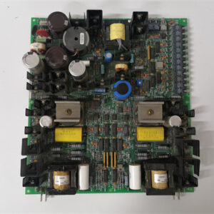
Thermocouple signals are the weakest signals in a turbine control system—microvolt-level measurements that are easily corrupted by noise and require precise cold junction compensation. The DS200TCCBG1A is GE’s purpose-built board for converting those tiny thermocouple voltages into usable digital values, and it’s one of the most critical boards in a Mark VI rack when you’re monitoring turbine exhaust temperatures (TET) or bearing temperatures.
The ‘CB’ in the part number indicates this is a thermocouple input board, distinct from the general-purpose analog boards (TCCAG1) and the RTD boards (TBSAG1). The ‘A’ revision improves the input amplifier stability and adds per-channel CJC compensation—the base model used a single CJC sensor for all channels, which could introduce errors if the termination board had temperature gradients. The TCCBG1A uses individual CJC sensors per channel (located on the associated termination board, read back through the backplane) and boasts a ±0.5°C total measurement accuracy. Compared to using a general-purpose analog board with an external thermocouple transmitter, the TCCBG1A is more accurate, faster, and integrates directly with the Mark VI’s temperature monitoring logic.
Key Technical Specifications
| Parameter | Value / Range |
|---|---|
| Manufacturer | General Electric (GE) |
| Part Number | DS200TCCBG1A |
| Board Type | Thermocouple Input Board |
| Number of Channels | 8 (isolated thermocouple inputs) |
| Input Range | ±100mV (typical thermocouple range) |
| Thermocouple Types | J, K, T, E, N, R, S, B (configurable per channel) |
| Resolution | 16-bit (65535 counts) |
| Accuracy | ±0.5°C total (including CJC, linearization) |
| CJC Method | Per-channel CJC (via connected termination board) |
| Input Impedance | >10MΩ (high impedance for thermocouple signals) |
| Common Mode Rejection | 100dB (DC to 60Hz) |
| Isolation | Channel-to-backplane: 1500Vrms |
| Update Rate | 50ms (all channels sampled simultaneously) |
| Input Power | 24 or 48 VDC (via backplane) |
| Mounting | VME rack (fits standard Mark VI backplane) |
| Operating Temp | 0°C to +60°C |
| Firmware | Version 2.0 or later recommended |
| Connectors | 1 x 96-pin DIN backplane connector |
Compatible Replacement Models
Replacement options depend on your thermocouple accuracy and CJC requirements.
✅ Drop-in Replacement: The DS200TCCBG1 (no ‘A’ suffix) is a direct drop-in—same pinout, same 8 channels, same ±100mV range. The differences: the base model uses a single CJC sensor for all channels (not per-channel), and its total accuracy is ±1.0°C instead of ±0.5°C. If your temperature monitoring doesn’t require the tightest accuracy (e.g., bearing temperature vs. exhaust temperature), the base model is a cheaper option.
⚠️ Software Compatible: The DS200TCCAG1A (general-purpose analog, 0-10V, 4-20mA) fits the rack but cannot handle thermocouple-level signals. You would need external thermocouple transmitters (4-20mA outputs), which would reduce accuracy and add cost. Not recommended for thermocouple applications.
⚠️ Software Compatible: The DS200TBSAG1A (RTD board) fits the rack but is designed for resistance sensors, not thermocouples. It cannot handle the microvolt-level signals of a thermocouple.
❌ Hardware Incompatible: Any discrete I/O board (TCCX series) uses different backplane pins and is not suitable for thermocouple inputs.
Frequently Asked Questions (FAQ)
What’s the difference between the TCCBG1A and the TCCAG1A?
The TCCAG1A is a general-purpose analog input board for 0-10V and 4-20mA signals. The TCCBG1A is a thermocouple input board designed for ±100mV signals. Key differences:
- Signal range: TCCBG1A handles ±100mV; TCCAG1A handles 0-10V.
- Input impedance: TCCBG1A is >10MΩ to avoid loading the thermocouple; TCCAG1A is >1MΩ.
- CJC: TCCBG1A has onboard CJC compensation; TCCAG1A does not.
- Linearization: TCCBG1A has built-in thermocouple linearization; TCCAG1A does not.
You cannot use a TCCAG1A for thermocouples without external amplification and CJC—you’d get no useful reading. The TCCBG1A is the correct board for thermocouple applications.
How does the cold junction compensation work on the ‘A’ revision?
The TCCBG1A uses per-channel CJC sensors located on the associated termination board (TBCBG1A). Each thermocouple channel has a dedicated CJC sensor that measures the temperature at the termination block—the “cold junction” where the thermocouple wire meets the copper terminal. The CJC reading is transmitted to the TCCBG1A via the backplane. The board then adds the CJC temperature to the thermocouple voltage reading (after linearization) to produce a true absolute temperature. The ‘A’ revision’s per-channel CJC is more accurate than the base model’s single CJC sensor because it compensates for temperature gradients across the termination board.
Can I use this board with a Mark VIe controller?
No—the TCCBG1A uses the older Mark VI backplane pinout. Mark VIe uses a different assignment and typically uses the IS200TCCBG1A for thermocouple inputs. Use the Mark VIe-specific board for new installations.
How do I test this board before installation?
Testing a thermocouple board requires a precision microvolt source:
- Visual inspection: Check for burnt or discolored components, especially around the input amplifiers and CJC compensation circuitry. Look for cracked solder joints on the backplane connector.
- Power-up test: Install the board in a test rack and apply 24 VDC. The board’s status LED (green) should illuminate within 2 seconds. If the LED is red or flashing, there’s a firmware or hardware issue.
- Firmware check: Read the firmware version via ToolboxST—should be 2.0 or later.
- CJC test: With no thermocouple connected, read the CJC temperature for each channel (via ToolboxST or the board’s diagnostic registers). It should match the ambient temperature within ±0.5°C. If the CJC reads room temperature correctly, the CJC sensors are working.
- Input test – voltage: Apply a precision 10.00mV DC (equivalent to about 250°C on Type K) to channel 1. The read value (in °C) should match the expected temperature ±0.5°C. Repeat for channels 1-8.
- Input test – thermocouple simulation: Use a thermocouple simulator to inject Type K signals at 0°C, 250°C, and 500°C. Verify the board reads within ±0.5°C of the injected temperature.
- Isolation test: Measure the resistance between an input terminal and the board’s ground—should be >10MΩ.
- Channel crosstalk: Apply a full-scale signal to channel 1 and a zero signal to channel 2. Read channel 2—it should be within ±0.1°C of its true value. If it’s higher, the isolation is compromised.
What’s the most common failure on this board?
Two issues specific to the thermocouple board:
- CJC sensor drift. The CJC sensors on the termination board can drift over time, causing a consistent offset on all thermocouple readings. The symptom: all channels read 2-3°C high or low. The fix: recalibrate the CJC sensors (requires GE-specific software and equipment) or replace the termination board.
- Input amplifier failure. The high-impedance input amplifiers are sensitive to ESD and overvoltage. If a thermocouple wire shorts to 24V DC, the input amplifier can be damaged. The symptom: one channel reads erratically (jumping values) or reads a fixed value regardless of the input. The amplifier is a surface-mount IC—not field-replaceable.
If I’m using this board in a SIL-rated safety application, what’s the recommended maintenance interval?
For SIL-2 and SIL-3 applications (IEC 61508), we recommend:
- Visual inspection: Every 6 months
- CJC test: Every 6 months (verify CJC sensors read ambient correctly)
- Input accuracy check: Every 12 months (verify each channel reads within ±0.5°C of a precision source)
- Full calibration: Every 5 years (requires a precision thermocouple calibrator and GE software)
What’s the lead time for a replacement TCCBG1A?
These boards are moderately available:
- New surplus: 2-4 weeks. The ‘A’ version with per-channel CJC is the most common.
- Refurbished: 1-2 weeks. Ensure the refurbisher tests the CJC—some shops only test the input channels.
- Used/as-is: Available, but the CJC sensors drift over time—used boards may be out of spec.
Is there a direct Mark VIe equivalent?
Yes—the IS200TCCBG1A (Mark VIe version). The backplane pinout is different, and the Mark VIe board may have different CJC schemes. If you’re migrating to Mark VIe, plan to replace all thermocouple boards as part of the rack conversion.
Which termination board should I use with the TCCBG1A?
The TCCBG1A is designed to interface with the DS200TBCBG1A (or DS200TBCBG1AAA) thermocouple termination board. The termination board provides the CJC sensors and the terminal connections. You can also use the base model DS200TBCBG1 termination board, but the per-channel CJC won’t work (you’ll get a single CJC reading for all channels). If you’re using the ‘A’ revision of the TCCBG1A, use the ‘A’ revision of the termination board for best accuracy.
What’s the correct thermocouple wire type for this board?
The TCCBG1A supports J, K, T, E, N, R, S, and B thermocouples. The most common in turbine applications are Type K (for exhaust temperature) and Type J (for bearing temperature). The thermocouple type is configured in software (ToolboxST) per channel—you can mix types on the same board. The board performs linearization based on the selected type. Always verify your connected thermocouple wire matches the software configuration—a Type K thermocouple configured as Type J will read about 20°C low at 500°C.
What’s the update rate for this board?
The TCCBG1A samples all 8 channels simultaneously at 50ms intervals—20Hz update rate. This is slower than the general-purpose analog board (10ms) because thermocouple signals are filtered more heavily to reduce noise. The 50ms update rate is more than sufficient for temperature monitoring, where thermal time constants are typically seconds to minutes. If you need faster temperature readings, you’d need a different board or use RTDs (which update faster).
Can I use this board with 125V DC?
No—the TCCBG1A is designed for 24 or 48 VDC only. The isolation rating is 1500Vrms between the inputs and the backplane, but the board’s power supply is not designed for 125V DC. Applying 125V DC will damage the board’s power supply circuitry.
What’s the maximum cable length for thermocouples on this board?
GE recommends a maximum of 300 feet (100 meters) for thermocouple cable runs. The limiting factor is the resistance of the thermocouple wire and the input impedance of the board (which is >10MΩ, so it’s not a significant load). Longer cable runs can pick up noise, which the board’s filtering helps with. For critical temperature measurements (exhaust temperature), keep cable runs as short as possible and use shielded thermocouple cable with the shield grounded at one end.
What’s the temperature range for this board?
The TCCBG1A itself is rated for 0°C to +60°C ambient. The thermocouple types it supports have much wider ranges:
- Type K: -200°C to +1260°C
- Type J: -200°C to +760°C
- Type T: -200°C to +350°C
- Type E: -200°C to +900°C
- Type N: -200°C to +1260°C
- Type R: 0°C to +1480°C
- Type S: 0°C to +1480°C
- Type B: +260°C to +1820°C
The board’s measurement range is limited by its ±100mV input range—at 100mV input, the board reads full scale. For Type K, 100mV corresponds to about 1370°C (you’ll never reach that in a turbine—exhaust temperature is typically 500-700°C).

CC-TAIM01 PLC DCS
05701-A-0301 PLC DCS
CC-PCNT02 PLC DCS
 Email: sales@plcfcs.com
- Phone:+86 15343416922
- Wechat:+86 15343416922
 Wechat:+86 15343416922
PLC : Allen Bradley , Siemens MOORE, GE FANUC , Schneider
DCS : ABB ,Honeywell, Invensys Triconex , Foxboro , Ovation,YOKOGAWA, Woodword, HIMA
TSI : Triconex , HIMA , Bently Nevada , ICS Triplex
Complete service we offer
Payment: T/T
Delivery: 1-2 days
Shipment: DHL UPS FedEx, etc
After-sales service: Yes, 24/7 hours