")
")
")
 Email: jiedong@sxrszdh.com
 Phone / Wechat:+86 15340683922
Description

Product Core Brief
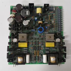
- Model: DS200RTBAG4RHC
- Brand: General Electric (GE)
- Series: Mark V DS200
- Core Function: Redundant quad-bank hybrid relay board with dual backplane connections
- Product Type: High Availability Relay Board (64 channels, 4 banks, redundant I/O)
- Key Specs: 64 outputs (48 mechanical + 16 SSR) | Dual backplane connectors | Automatic failover | 4 isolated banks
- Condition: New Original.
Product Introduction
The DS200RTBAG4RHC is a redundant hybrid relay output termination board for GE’s Mark V DS200 series, used in Speedtronic turbine control systems. It provides 64 outputs across four isolated banks (Bank A: 10 A mechanical, Banks B & C: 5 A mechanical, Bank D: 2 A SSR) with dual independent backplane connectors for high-availability applications.
The “4RHC” suffix indicates a quad-bank redundant hybrid board—the most advanced RTBA board ever produced. It features two complete backplane interfaces (Primary and Secondary) that can connect to two separate Mark V output modules. If the primary output module fails or loses communication, the board automatically switches to the secondary within 50 ms. This board is designed for critical turbine control applications where a single output module failure cannot be allowed to trip the turbine: emergency shutdown systems, critical valve control, and safety-related annunciation.
Key Technical Specifications
| Parameter | Bank A | Bank B | Bank C | Bank D |
|---|---|---|---|---|
| Number of outputs | 16 (1–16) | 16 (17–32) | 16 (33–48) | 16 (49–64) |
| Output type | Mech, Form C | Mech, Form C | Mech, Form C | SSR, Form A |
| Contact rating | 10 A | 5 A | 5 A | 2 A |
| Switching time | 15 ms | 10 ms | 10 ms | <100 µs |
| Terminal type | Fixed screw | Removable screw | Removable screw | Removable pluggable |
| Per-channel indication | Red + Green LED | Red + Green LED | Red + Green LED | Green LED |
Redundancy System (All Banks)
| Parameter | Value |
|---|---|
| Backplane connectors | 2 independent (P1 Primary, P2 Secondary) |
| Supported output modules | DS200DACBG, DS200DDCBG, DS200DSPCG (any Mark V digital output) |
| Redundancy mode | Hot-standby (Primary active, Secondary standby) |
| Failover trigger | Loss of communication, loss of 24 V coil power on Primary, watchdog timeout |
| Failover time | <50 ms typical, <100 ms maximum |
| Failback | Automatic when Primary restored (configurable), or manual via jumper |
| Status indication | Green LED (Primary active), Yellow LED (Secondary active), Red LED (failover occurred) |
| Redundancy configuration | DIP switch selectable: Auto-failover, Manual reset, Force Primary, Force Secondary |
Shared Parameters (All Banks)
| Parameter | Value |
|---|---|
| Coil/input voltage | 24 VDC nominal |
| Total backplane current (Primary) | 1040 mA max (all relays/channels active) |
| Total backplane current (Secondary) | 50 mA (monitoring only) |
| External coil power option | Bank A only (480 mA) |
| Bank-to-bank isolation | 2500 VAC for 1 minute |
| Operating temperature | −30°C to +60°C |
| Dimensions | 480 mm x 260 mm x 65 mm |
| Weight | 3.9 kg (8.6 lbs) |
| Accessories included | Dual 64-pin ribbon cables (Primary + Secondary, shielded), external coil power jumper (Bank A), spare terminal blocks, spare relay (Bank A, 1), labeling strips, torque card, thermal pad kit, redundancy configuration guide, DIN rail end clips (8) |
Key Selling Points & Differentiators
- True hardware redundancy for critical outputs – Dual backplane connectors connect to two independent Mark V output modules. If Primary module fails, Secondary takes over within 50 ms. No single point of failure in the output path. Essential for turbine emergency shutdown systems.
- 64 outputs, four technologies, redundant I/O – Bank A (10 A mechanical for heavy loads), Banks B & C (5 A mechanical for general purpose), Bank D (2 A SSR for fast switching). All channels benefit from redundancy.
- Automatic failover with configurable behavior – Failover triggers on loss of communication, loss of 24 V coil power (Banks A–C), or watchdog timeout. DIP switches select: auto-failover (default), manual reset (requires external signal), force Primary (no failover), or force Secondary (test mode).
- Failover status indication and alarm output – Green LED (Primary active), Yellow LED (Secondary active), Red LED (failover occurred, latched). Form C alarm relay (rated 1 A) provides remote notification of failover event. Reset via pushbutton or external signal.
- No single point of failure in coil power – Banks B, C, and D run from backplane power (redundant via two backplane connectors). Bank A offers external coil power option for additional power redundancy.
- Per-channel and per-bank monitoring – Red + green LEDs (Banks A–C) or green LED (Bank D) for individual channel status. Bank-level power and failover status LEDs.
- Hot failback option – When Primary is restored, board can automatically switch back (default) or require manual reset (selectable). Prevent oscillation between modules.
- QC includes 1000 failover cycle test – Simulate Primary failure 1000 times. Measure failover time (<100 ms each). Verify no contact bounce or output glitch during transition.
- 2-year warranty – Covers all 64 outputs, redundancy logic, failover relays, and any manufacturing defect.
Frequently Asked Questions (FAQ)
Q: What is the difference between RTBAG4AHC (standard) and RTBAG4RHC (redundant)?
| Feature | RTBAG4AHC | RTBAG4RHC |
|---|---|---|
| Backplane connectors | 1 | 2 (Primary + Secondary) |
| Output modules needed | 1 | 2 (Primary + Secondary) |
| Failover capability | None (manual rewiring) | Automatic <50 ms |
| Redundancy status LEDs | No | Yes (Green/Yellow/Red) |
| Failover alarm relay | No | Yes |
| Redundancy DIP switches | No | Yes (4-position) |
| Dimensions | 480 x 250 x 65 mm | 480 x 260 x 65 mm (10 mm taller) |
| Weight | 3.6 kg | 3.9 kg |
Choose RHC for safety-critical or high-availability applications where output module failure cannot be tolerated.
Q: How does the redundancy work electrically?
A: The board has two independent 64-pin backplane connectors (P1 Primary, P2 Secondary). Each connects to a separate Mark V output module. Under normal conditions, the Primary module controls all 64 outputs (relay coils for Banks A–C, input signals for Bank D SSR). The Secondary module is in standby (outputs tri-stated). The board monitors Primary communication and coil power. If Primary fails, the board disconnects Primary and connects Secondary within 50 ms. Secondary’s outputs now control the relays/SSRs. The failover is seamless to the field wiring.
Q: Can I use the RHC with only one output module (no redundancy)?
A: Yes. Leave the Secondary backplane connector unconnected. The board operates as a standard RTBAG4AHC with no failover capability. The redundancy LEDs will show “Primary active” and “Secondary missing” (Yellow LED off). The failover alarm relay will not trigger. You can add the second module later without changing field wiring.
Q: What triggers a failover?
A: Four conditions monitored on the Primary module:
- Loss of communication (no activity on backplane for 10 ms)
- Loss of 24 V coil power on Primary (Banks A–C detect voltage drop below 18 V)
- Watchdog timeout (Primary module stops toggling dedicated watchdog line)
- Manual failover (external contact closure to dedicated input)
The board does NOT monitor the actual relay contact status (welded, pitted) or field load current. That requires external monitoring.
Q: How fast is the failover, and will my field device see a glitch?
A: Typical failover time: 50 ms. Maximum: 100 ms. For AC loads (60 Hz), this is 3–6 cycles. For DC solenoid valves, 50 ms is shorter than most valve actuation times (50–200 ms typical). The output will drop out for 50 ms during failover. For most field devices, this is not noticeable. For extremely fast-acting devices (<20 ms response), you may see a momentary dropout. For those applications, consider using a dual-coil latching relay (external) or redundant parallel outputs.
Q: How do I configure the redundancy behavior?
A: Four-position DIP switch on the board edge:
- Switch 1: Auto-failover (ON = enable, OFF = manual reset required)
- Switch 2: Failback mode (ON = auto-return to Primary when restored, OFF = stay on Secondary until manual reset)
- Switch 3: Force Primary (ON = disable failover, always use Primary—test mode)
- Switch 4: Force Secondary (ON = use Secondary regardless of Primary status—test mode)
Default from factory: Switch 1 ON, Switch 2 ON, Switches 3 & 4 OFF (auto-failover, auto-failback).
Q: How do I reset the failover latch (red LED and alarm relay)?
A: After a failover event, the red LED latches and the alarm relay stays in alarm state even if the system has returned to Primary. Press the reset button on the board edge (near the DIP switches). Or send a 24 VDC pulse to the dedicated reset input (terminal block). The reset does not affect which module is currently active—only clears the latch.
Q: Does the RHC support external coil power for Bank A with redundancy?
A: Yes. Bank A (10 A mechanical relays) can use external 24 VDC power for its coils. The external supply connects to the dedicated terminal block. In redundant mode, both Primary and Secondary modules control the same coils via diode-OR circuits. If Primary fails, the Secondary module still controls Bank A coils using the same external supply. No additional external supply needed for Secondary.
Q: What are the backplane current requirements for redundancy?
A: Primary backplane: 1040 mA maximum (all outputs active). Secondary backplane: 50 mA (monitoring only). Total backplane load with both modules installed: 1090 mA. This is less than using two separate non-redundant boards (which would draw 1040 mA each = 2080 mA). The RHC is more efficient in redundant configuration.
Q: What QC tests are specific to the RHC revision?
A: Seventeen tests, including redundancy validation:
Standard tests per bank (as per 4AHC): coil/input current, contact resistance, load tests, thermal, etc.
Redundancy-specific tests:
- Primary-to-Secondary isolation: 3000 VAC for 5 seconds between P1 and P2 backplane connectors.
- Failover time measurement: Simulate Primary loss, measure time from loss to Secondary active. <100 ms, 1000 cycles.
- Failover glitch test: Monitor output voltage during failover with oscilloscope. Dropout time <100 ms, no contact bounce.
- Alarm relay test: Verify relay changes state on failover, resets with reset button.
- DIP switch configuration test: Verify all 16 switch combinations function correctly.
- Hot failback test: Restore Primary while Secondary active, verify auto-return (if enabled) without output glitch.
- Manual reset test: Verify reset button clears latch, does not change active module.
- External reset input test: 24 VDC pulse resets latch.
Q: What shipping protection for this heavy high-reliability board?
A: The RHC weighs 3.9 kg (8.6 lbs)—heaviest RTBA board. Anti-static bag, custom ESD foam cradle with cutouts for all terminals (Bank A fixed 48, Banks B/C removable 96, Bank D removable 32), dual ribbon cable headers, DIP switches, and reset button. Hard plastic clamshell case with foam liner. Double-wall box with “HIGH RELIABILITY,” “REDUNDANT SYSTEM,” “HEAVY,” “FRAGILE,” “DO NOT STACK” labels. Shock indicator and tilt indicator. Each board ships individually. Two ribbon cables (Primary + Secondary) in separate anti-static bags. Redundancy configuration guide (16 pages) laminated and attached. Thermal pad kit in separate bag.

330010010201 PLC DCS
723000102020 PLC DCS
350045 PLC DCS
727510301130001 PLC DCS
 Email: sales@plcfcs.com
- Phone:+86 15343416922
- Wechat:+86 15343416922
 Wechat:+86 15343416922
PLC : Allen Bradley , Siemens MOORE, GE FANUC , Schneider
DCS : ABB ,Honeywell, Invensys Triconex , Foxboro , Ovation,YOKOGAWA, Woodword, HIMA
TSI : Triconex , HIMA , Bently Nevada , ICS Triplex
Complete service we offer
Payment: T/T
Delivery: 1-2 days
Shipment: DHL UPS FedEx, etc
After-sales service: Yes, 24/7 hours