")
")
")
 Email: jiedong@sxrszdh.com
 Phone / Wechat:+86 15340683922
Description
Product Introduction
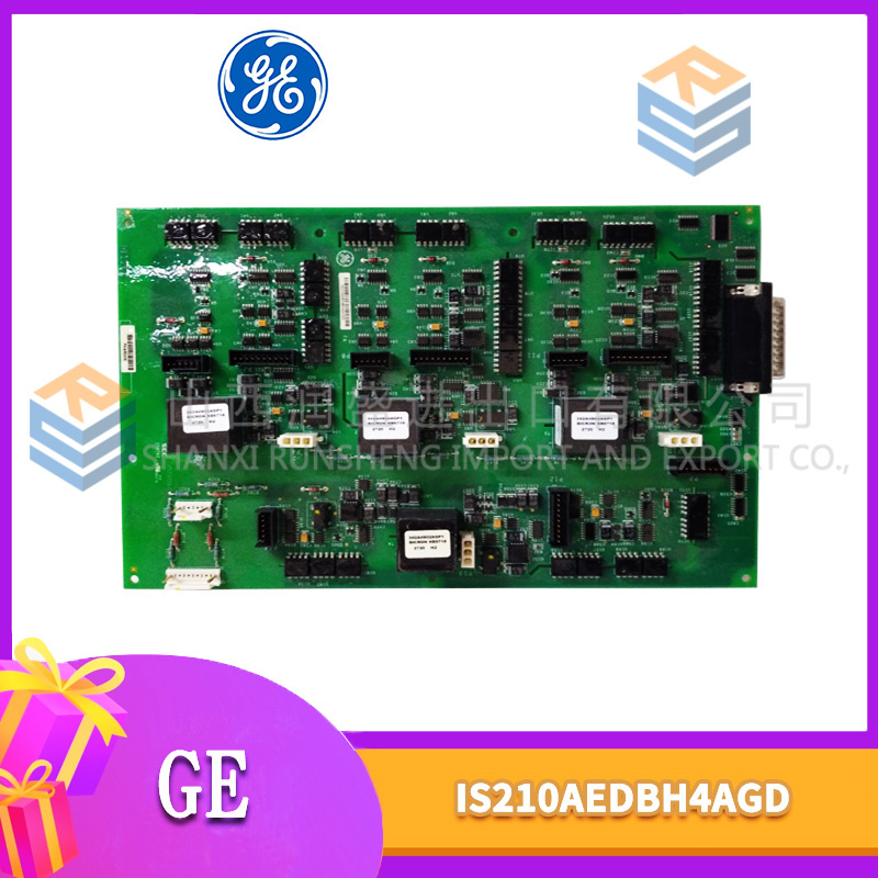
The DS200PCCAG2ADB is the diagnostic powerhouse of the G2 series. The standard G2A gives you a fault LED and a 9600 baud debug port. This board gives you a full black box recorder for your turbine control logic.
The “DB” suffix adds a dedicated 512KB static RAM buffer for fault logging, a CPLD that captures backplane address/data at the moment of a crash, and an upgraded UART that runs at 115200 baud (12x faster than standard). Same 25MHz 68EC030, same 2MB RAM, same FPU as the G2A. But when something goes wrong, the DB variant captures 1,000 instructions of execution trace plus the state of every I/O slot. To be blunt, the standard G2A leaves you guessing after a watchdog timeout. The ADB variant tells you exactly which line of code executed last. For intermittent faults that take weeks to reproduce, this board is indispensable.
Key Technical Specifications
| Parameter | Value |
|---|---|
| Manufacturer | GE General Electric |
| Series | Mark V Turbine Control |
| Board Type | CPU / Core Controller |
| Part Number | DS200PCCAG2ADB |
| Revision | G2A with DB (diagnostic boost) |
| Processor | Motorola 68EC030 @ 25MHz |
| FPU | External 68LC040-compatible |
| RAM | 2MB (non-ECC standard) |
| Flash | 2MB |
| Backup RAM (config) | 256KB |
| Diagnostic Buffer | 512KB (battery-backed, non-volatile) |
| Fault Capture | 32-bit address, 16-bit data, 8-bit status |
| Execution Trace | 1,000 instructions (continuous) |
| Debug Port | RS-232, 115200 baud (switchable to 9600) |
| Diagnostic LEDs | 8: Power, Run, Fault, Battery, FPU, Addr, Data, Trace |
| Operating Temp | 0°C to 55°C |
| Backplane Connector | 3x 96-pin DIN 41612 |
| Power Draw | 5V @ 1.05A |
Compatible Replacement Models
✅ Drop-in Replacement: DS200PCCAG2A
Standard version without diagnostic buffer. Same pinout. Swaps directly. Lacks fault capture and high-speed debug. Debug port runs at 9600 baud.
✅ Drop-in Replacement: DS200PCCAG5DB
Third-generation board with diagnostic boost (4MB RAM, faster FPU). Same pinout. Swaps directly. Requires program recompilation if your code uses G2A-specific memory timings. Estimate 4-8 hours.
⚠️ Software Compatible: DS200PCCAG1ADB
First-generation diagnostic board (16MHz, 1MB RAM, no FPU). Same pinout. Requires program recompilation to fit in smaller memory and to work around missing FPU. Estimate 8-16 hours.
❌ Hardware Incompatible: DS200PCCAG2 (non-A)
Original G2 release lacks the diagnostic buffer address lines on the backplane. The ADB board will fit but fault capture data will be garbage—the pins are unconnected.
Frequently Asked Questions (FAQ)
How do I retrieve the execution trace after a crash?
Connect to the debug port (115200 baud, 8-N-1). Use PCC_Diag version 2.5 or higher. Commands:
debug ontrace show last(displays last 100 instructions before crash)trace show full(displays all 1,000 instructions, takes about 30 seconds)
The trace includes instruction addresses and raw opcodes. You’ll need your program’s map file (generated by the Mark V Toolbox) to translate addresses to function names. Without the map file, you get hex addresses only—still useful for identifying which task crashed.
My ADB board shows the DATA LED flashing in a repeating pattern (3 fast, 3 slow). What does this mean?
That’s the “data bus error” pattern. The board detected a bad read or write cycle on the backplane. The pattern encodes the slot number: 3 fast = slot 3, 3 slow = error type (bus timeout). Check the I/O board in slot 3. It may be failing or not seated properly. The DATA LED pattern is documented in GE manual GEI-100845, Table 4-3. We’ve seen this pattern most often with DS200LUVAG1A LAN boards that have marginal backplane connections.
What’s the typical failure mode on the ADB board?
The diagnostic buffer’s battery fails, same as the G1ADB. The ADB uses a BR1225 for the main config and a second BR1225 for the diagnostic buffer (location U19, near the CPLD). When the diagnostic battery dies, fault show returns “buffer corrupt.” The board still runs fine. Replace both batteries every five years. We sell a kit with both batteries and a desiccant pack for $15.
Can I use the ADB board’s high-speed debug port to monitor real-time performance?
Yes, but with limits. The debug port can stream execution trace live at 115200 baud. However, the board can generate trace data faster than the serial port can transmit. At full speed, you’ll lose about 30% of the trace data. For real-time monitoring, use the trace rate command to sample every 10th instruction. For post-crash analysis, the onboard buffer is better—it captures everything without dropping data.
How do I convert a standard G2A to ADB specifications?
You can’t practically. The ADB board uses a different PCB with 12 additional ICs (CPLD, SRAM, UART, level shifters, LEDs, and passives). The board layout is completely different. We’ve seen one attempt. The cost in parts (150) and labor (8+ hours) exceeded the price of a used ADB board (800-1,200). Just buy the ADB.
My ADB board triggers fault capture on every power-up. Is this normal?
No. The board should capture faults only when a watchdog timeout or bus error occurs. If it captures on every boot, the CPLD may have a stuck input. Run fault clear. Cycle power. If the fault returns within 1 minute without any application code running (bootloader only), the CPLD is likely damaged. We can replace the CPLD (Altera EPM7032) for $200, but it requires desoldering a 44-pin PLCC. Sometimes it’s cheaper to replace the board.
What’s the lead time for a DS200PCCAG2ADB from surplus stock?
2-5 weeks. The ADB variant is rare—about 2% of G2A boards shipped with diagnostic boost. GE sold these primarily to turbine OEMs for development and field service. We maintain about 8 units in stock. Price is typically 60-80% higher than a standard G2A. For chronic intermittent faults, it’s worth every penny.
Do you offer a trace analysis service for ADB capture data?
Yes. Export the trace using trace export > trace.txt. Email us the file along with your program’s map file (.MAP from Toolbox). We analyze the instruction stream, identify the faulting task, and correlate with I/O slot timing. Cost is $350 per analysis. Includes a written report with line numbers (if you provide source code) or function names (if you provide map file only). Turnaround is 3 business days. If we can’t identify the root cause, you don’t pay. This service has resolved about 75% of intermittent fault cases we’ve seen. The remaining 25% required hardware oscilloscope analysis of the backplane.


AMAT 0140-02349 PLC DCS
AMAT 0150-00179 PLC DCS
AMAT 0140-01156 PLC DCS
 Email: sales@plcfcs.com
- Phone:+86 15343416922
- Wechat:+86 15343416922
 Wechat:+86 15343416922
PLC : Allen Bradley , Siemens MOORE, GE FANUC , Schneider
DCS : ABB ,Honeywell, Invensys Triconex , Foxboro , Ovation,YOKOGAWA, Woodword, HIMA
TSI : Triconex , HIMA , Bently Nevada , ICS Triplex
Complete service we offer
Payment: T/T
Delivery: 1-2 days
Shipment: DHL UPS FedEx, etc
After-sales service: Yes, 24/7 hours