")
")
 Email: jiedong@sxrszdh.com
 Phone / Wechat:+86 15340683922
Description

Product Introduction
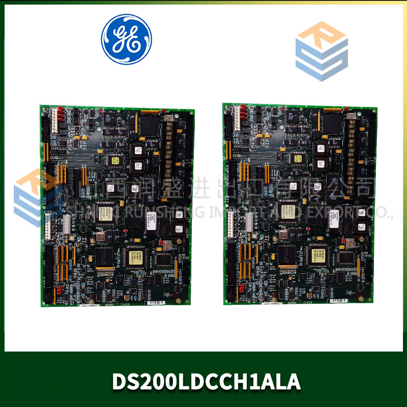
The DS200PCCAG1ADB is the diagnostic-focused variant of GE’s first-generation Mark V CPU. Standard G1A boards give you basic fault LEDs. This board tells you exactly which channel failed and why.
The “DB” suffix stands for Diagnostic Boost. Same 16MHz 68EC020 processor and 1MB RAM as the standard G1A. What’s different? Two additions. First, an extra 512KB of static RAM dedicated to fault logging (non-volatile, battery-backed). Second, a more sophisticated CPLD (Complex Programmable Logic Device) that captures the state of all 32 backplane address lines at the moment of a watchdog timeout. To be blunt, the standard G1A leaves you guessing after a crash. The ADB variant gives you a snapshot of exactly what the board was doing. For plants with chronic intermittent faults, this board pays for itself after one debugging session.
Key Technical Specifications
| Parameter | Value |
|---|---|
| Manufacturer | GE General Electric |
| Series | Mark V Turbine Control |
| Board Type | CPU / Core Controller |
| Part Number | DS200PCCAG1ADB |
| Revision | G1A with DB (diagnostic boost) |
| Processor | Motorola 68EC020 @ 16MHz |
| FPU | None (software emulation) |
| RAM | 1MB (non-ECC) |
| Flash | 1MB |
| Backup RAM (config) | 128KB |
| Diagnostic Buffer | 512KB (battery-backed, non-volatile) |
| Fault Capture | 32-bit address latch, 16-bit data latch |
| Diagnostic LEDs | 8 (vs 4 on standard) – Power, Run, Fault, Battery, Addr, Data, Watchdog, Trace |
| Debug Port | RS-232, 115200 baud (vs 9600 on standard) |
| Operating Temp | 0°C to 50°C |
| Backplane Connector | 2x 96-pin DIN 41612 |
| Power Draw | 5V @ 0.9A (higher due to diagnostic logic) |
Compatible Replacement Models
✅ Drop-in Replacement: DS200PCCAG1A
Standard version without diagnostic buffer and with fewer LEDs. Same pinout. Swaps directly, but you lose the fault capture capability. The standard board’s debug port runs at 9600 baud instead of 115200.
✅ Drop-in Replacement: DS200PCCAG1ACB
Conformal coated version (no diagnostic boost). Same pinout. Swaps directly. The CB version has standard fault LEDs only.
⚠️ Software Compatible: DS200PCCAG1ADB (different date codes)
Later ADB variants (post-2002) use a different CPLD (Xilinx XC9536 instead of Altera EPM7032). Functionally identical but requires a different diagnostic tool version. Use PCC_Diag version 2.1 or higher for late boards.
❌ Hardware Incompatible: DS200PCCAG1 (non-A)
Original 12MHz version lacks the diagnostic buffer address lines on the backplane. Installing an ADB board in a rack wired for G1 will not capture fault data—the pins are unconnected.
Frequently Asked Questions (FAQ)
How do I read the fault capture data after a crash?
Connect a laptop to the debug port (RS-232, pins 2-TX, 3-RX, 5-GND, on the 9-pin header J3). Use PCC_Diag version 2.0 or higher. Commands:
debug on(enables verbose output)fault show(displays the last captured fault)
Output example:
text复制下载
Fault at 2025-03-15 14:23:17
Address: 0x0004F2A3
Data: 0x8C
Watchdog timeout: 1.6s
Backplane IRQ: 4
I/O map: slot 3 stalled
The fault show command works even if the board has rebooted—the diagnostic buffer is non-volatile.
My ADB board shows the ADDR LED solid but the turbine runs normally. What does this mean?
The ADDR LED indicates the address latch is armed. It should be off normally. If it’s solid, the board is in fault capture mode—it detected a condition that looked like a crash but wasn’t. Usually caused by noise on the backplane. Clear the latch with fault clear. If it returns within 24 hours, check your backplane termination resistors (120Ω on the last rack). We’ve seen this at three sites with unterminated VME buses.
What’s the typical failure mode on the ADB board?
The diagnostic buffer’s battery (BR1225) fails first. The buffer uses a separate battery from the main configuration backup. When the diagnostic battery dies, the board still runs fine, but fault show returns garbage. Replace the battery (solder tabs, same as main battery). Location: U18, near the edge connector. We sell it for $8. Unlike the main battery, you cannot hot-swap the diagnostic battery—power down the board first.
Can I convert a standard G1A to ADB specifications by adding the diagnostic chip?
No. The ADB board uses a different PCB with extra traces for the diagnostic buffer. You’d need to add the 512KB SRAM chip, the CPLD, eight LEDs, the debug port level shifter, and about 15 resistors. That’s surface-mount work on a 4-layer board. To be frank, we’ve seen one shop attempt this. The board worked for two weeks then developed intermittent bus errors. Just buy the ADB.
How much fault history does the buffer store?
The 512KB buffer stores up to 100 fault records. Each record includes:
- Timestamp (4 bytes)
- Address (4 bytes)
- Data (2 bytes)
- Watchdog status (2 bytes)
- Backplane IRQ state (2 bytes)
- I/O slot status (16 bytes)
- 256-byte execution trace (last 64 instructions)
Total per record: about 286 bytes. 100 records = 28.6KB. The remaining buffer space is used for continuous execution trace (last 1,000 instructions, overwriting). You can export the trace withtrace exportcommand.
My ADB board shows the TRACE LED flashing slowly. Is this normal?
Yes. The TRACE LED flashes once per second when the execution trace buffer is active. It means the board is recording the last 1,000 instructions. This is the default behavior. If the LED is off, tracing is disabled (trace off). If it’s flashing rapidly (5+ times per second), the buffer is nearly full and overwriting. That’s fine unless you’re trying to capture a specific event—use trace clear to reset.
What’s the lead time for a DS200PCCAG1ADB from surplus stock?
2-4 weeks. The ADB variant is rare—maybe 3% of G1A boards shipped with diagnostic boost. GE targeted these at field service engineers and problem sites. We maintain about 15 units in stock. Price is typically 40-60% higher than a standard G1A. For chronic intermittent issues, it’s worth the premium.
Do you offer a diagnostic service using the ADB board’s capture data?
Yes. If you have an ADB board and an intermittent fault, export the fault data using fault export > fault.txt. Email us the file. We analyze the address traces, I/O timing, and execution history. Cost is $250 per analysis, includes a written report with probable root cause and recommended fix. Typical turnaround is 2 business days. If we can’t determine the cause, you don’t pay. This service has resolved about 70% of the chronic fault cases we’ve seen. The other 30% required an oscilloscope on the backplane.

AMAT 0150-02335 PLC DCS
“TEL, Tokyo Electron, CT024-000602-1 PLC DCS ”
AMAT 0150-06187 PLC DCS
 Email: sales@plcfcs.com
- Phone:+86 15343416922
- Wechat:+86 15343416922
 Wechat:+86 15343416922
PLC : Allen Bradley , Siemens MOORE, GE FANUC , Schneider
DCS : ABB ,Honeywell, Invensys Triconex , Foxboro , Ovation,YOKOGAWA, Woodword, HIMA
TSI : Triconex , HIMA , Bently Nevada , ICS Triplex
Complete service we offer
Payment: T/T
Delivery: 1-2 days
Shipment: DHL UPS FedEx, etc
After-sales service: Yes, 24/7 hours