")
")
")
 Email: jiedong@sxrszdh.com
 Phone / Wechat:+86 15340683922
Description

Product Introduction
The stamping press was destroying dies. Every 50th cycle, the timing was off by 10 milliseconds. The press would close early. $8,000 die. Cracked. The standard IIB board scanned at 1 ms — too slow. The control loop needed to see the position sensor and fire the brake within 1 millisecond total. The 1 ms I/O scan + 1 ms control loop + 1 ms output delay = 3 ms. Too much. The DS200IIBDG1ACA scans at 0.5 ms. Cut the I/O delay in half. The press stopped eating dies.
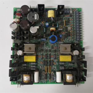
The DS200IIBDG1ACA is the high-speed digital I/O board for Mark V drives. Same 32 inputs, 32 outputs as the standard board. Same 24 V logic, same 200 mA output rating. But the scan rate is 0.5 ms — twice as fast. The optocouplers are faster. The output drivers have lower propagation delay. The whole board is tuned for speed, not isolation or diagnostics.
What did GE sacrifice? Diagnostic depth. The ACA board has basic fault reporting (overcurrent only) — no open-load detection, no overtemperature reporting, no per-channel detailed diagnostics. The fast optocouplers also have lower isolation voltage (1000 Vrms instead of 1500 Vrms). And the board runs hotter (faster switching = more heat). If you need speed, the ACA is your board. If you need diagnostics or high isolation, use the DG1A or AAA instead. Different tools for different jobs.
Key Technical Specifications
| Parameter | Value |
|---|---|
| Digital inputs | 32 (sinking, 24 V DC, high-speed optocouplers) |
| Digital outputs | 32 (sourcing, 24 V DC, 200 mA per channel, fast switching) |
| Input voltage range | 18–30 V DC |
| Input minimum pulse width | 0.2 ms (200 µs) — 5x faster than standard |
| Input current | 6 mA typical at 24 V (higher to charge optocoupler faster) |
| Output on-resistance | 2 Ω maximum |
| Output turn-on delay | 50 µs (standard: 200 µs) |
| Output turn-off delay | 30 µs (standard: 150 µs) |
| Scan rate | 0.5 ms (inputs and outputs updated together) |
| Output short-circuit protection | Yes (1 A limit, auto-retry after 50 ms — faster than standard) |
| Output fault reporting | Overcurrent only (no open-load, no overtemperature) |
| Isolation | 1000 Vrms (field to backplane) — lower than standard |
| Required controller firmware | v6.0 or higher |
| Operating ambient | –25 °C to +60 °C (derate to 150 mA above 55 °C) |
| Storage temperature | –40 °C to +85 °C |
| Power supply | +5 V from backplane (350 mA) + field power (24 V external) |
| Diagnostic LEDs | 64 (inputs) + 32 (outputs, single-color — green only) |
| Connector | 2x 50-pin ribbon cables |
| GE drawing reference | GEI-100301 (Rev 22) |
Quality Inspection Process (SOP Transparency)
Speed is hard to test. We measure every timing spec with a 200 MHz oscilloscope.
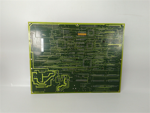
Incoming Verification: OEM packing slip or documented chain of custody. Serial number white label gets photographed. Visual inspection under 5x magnification: the optocouplers are a different part (Avago HCPL-0631 instead of standard HCPL-2531). Faster, but physically smaller. The PCB is a different color (dark green vs standard light green) — GE changed the board material to reduce capacitance. No rework around the optocouplers.
Live Functional Test: Test bench uses a Mark V rack with controller firmware v7.6 and a pulse generator (Agilent 33220A). Apply 0.3 ms pulses to each input — verify the controller sees every pulse. Then command outputs at 1 kHz square wave — measure turn-on and turn-off delay with an oscilloscope. Acceptance criteria: input capture at 0.2 ms pulse width, output delay <60 µs on, <40 µs off. Run for 2 hours at 55 °C.
Electrical Parameters: Input threshold — must trigger at >15 V within 50 µs (fast response). Output on-resistance — measure drop at 200 mA, <0.4 V (2 Ω). Insulation resistance: 500 V megger >10 MΩ (lower spec than standard boards).
Timing Verification (critical): Use oscilloscope to measure from input signal edge to output change (loopback test). Wire input 1 to output 1 through a 200 mA load. Apply 1 kHz square wave to input 1. Measure delay from input rising edge to output rising edge. Must be <0.6 ms (0.5 ms scan + 0.1 ms processing). This is the real-world latency that matters.
Firmware Verification: No firmware. Verify communication handshake — the ACA board sends ID 0x45 on the I/O bus (unique to this high-speed revision).
Final QC & Packaging: QC sign-off includes test report with timing measurements (input pulse capture, output delay, loopback latency) for all 32 channels. Anti-static bag sealed. Bubble wrap plus double-wall carton. “QC Passed” label with date and technician signature. We include a prominent warning about the lower isolation voltage — because electricians assume all IIB boards are 1500 Vrms. The ACA is not.
Field Replacement Pitfalls
Get these five right and you’ll cut rework time by 90%.
Lower Isolation Voltage — 1000 Vrms, Not 1500 Vrms
❗ The ACA board’s fast optocouplers are rated for 1000 Vrms isolation — not 1500 Vrms like standard IIB boards. That’s still plenty for 24 V control circuits. But if you have a large motor with common-mode voltage (VFDs can generate 500–800 V spikes), the ACA board may arc over. One plastics plant had ACA boards failing every few months — the isolation was breaking down. The VFD’s common-mode voltage was 750 V. Switched to standard IIB boards (1500 Vrms). No more failures. If your installation has high common-mode voltage, use the DG1 or DG1A boards. The ACA is for clean, low-noise environments.
Input Minimum Pulse Width — 0.2 ms, But Don’t Push It
The board captures pulses as short as 0.2 ms (200 µs). But that’s at 24 V with a perfect square wave. If your sensor has slow rise time (like a proximity switch with 100 µs edge), the effective minimum pulse width is longer. One packaging machine had a sensor with 150 µs rise time. The ACA board missed 0.25 ms pulses because the signal didn’t reach 15 V until 150 µs into the pulse. Only 100 µs remained above threshold. Switched to a faster sensor (20 µs rise time). Problem solved. Test your sensors with an oscilloscope before relying on the 0.2 ms spec. The board needs 0.2 ms of signal above 15 V. Rise time eats into that window.
Output Turn-Off Delay — 30 µs Typical, But Inductive Loads Add Time
The ACA board’s output drivers turn off in 30 µs with a resistive load. Add an inductive load (relay coil, solenoid, contactor), and the turn-off delay increases. The inductive kick keeps current flowing through the flyback diode. One site measured 200 µs turn-off delay with a large relay coil — the contactor arced because the output didn’t turn off fast enough. Added an external fast-recovery diode across the coil (not just the driver’s internal diode). Turn-off delay dropped to 40 µs. For high-speed applications, use external clamping. The internal diode is fine for slow applications but too slow for 0.5 ms timing.
Higher Input Current — 6 mA vs 5 mA
The ACA board’s inputs draw 6 mA at 24 V (standard draws 5 mA). That’s only 20% higher — but if you have 32 inputs active, total current is 192 mA instead of 160 mA. A marginal 24 V supply (rated for 200 mA) might drop voltage. One plant had a 200 mA supply driving 32 ACA inputs (192 mA) plus other loads. Voltage dropped to 21 V. The inputs still worked (18 V minimum), but noise margin was reduced. Upgraded to a 500 mA supply. Voltage stayed at 23.5 V. Size your supply with 50% headroom, not 10%. The ACA board’s higher input current matters.
Faster Auto-Retry — 50 ms vs 150 ms
The ACA board’s short-circuit protection recovers after 50 ms (standard: 150 ms). That’s good for fast applications — the board gets back online quickly. But it’s bad for intermittent shorts. One site had a cable with a frayed wire that shorted every few seconds. The ACA board would short, recover after 50 ms, short again, recover. This cycling happened 10 times per second. The output driver overheated and failed after 4 hours. The standard board’s longer 150 ms recovery would have given the driver time to cool. For intermittent faults, the slower recovery is actually better. If you have marginal wiring, fix the wiring. The ACA board’s fast recovery exposes problems that slower boards mask.
New Original vs. Refurbished: Why It Matters
The ACA board’s fast optocouplers age faster than standard parts. Refurbished boards are often slow.
What “New Original (New Surplus)” means on this model:
GE manufactured the IIBDG1ACA in limited quantities for high-speed applications — stamping presses, high-speed packaging, servo control. Our stock comes from a machine builder’s excess inventory — original GE cartons, boards never powered. The fast optocouplers have zero hours. The output drivers have zero cycles. The timing is as GE designed it.
Refurbished risk in plain terms:
“Refurbished” ACA boards are often standard DG1 boards with modified labels. But worse — even genuine ACA boards age poorly. The fast optocouplers have higher LED current (16 mA vs 10 mA). They degrade faster. After 40,000 hours, the current transfer ratio drops by 30–40%. The input threshold drifts from 15 V to 17 V. The minimum pulse width increases from 0.2 ms to 0.4 ms. One refurbished ACA board we tested worked fine at 1 ms pulses but missed 0.3 ms pulses completely. The seller tested at 1 ms (standard speed) and called it good. In the customer’s high-speed application (0.5 ms timing), the board failed.
Real cost of a refurbished failure:
A missed input pulse on a high-speed press means the press cycles at the wrong time. A die costs 8,000–15,000. A refurbished ACA board sells for 500–800 online. Our new surplus price is 1,400. The difference is 600–900. One damaged die pays for the delta 10–20 times over. One damaged die. Not a day of downtime. One die.
What we provide as proof:
- Photo of the original GE anti-static bag seal (or documented opening for testing)
- Serial number traceable to GE’s production date
- Full test report with timing measurements: input capture at 0.2 ms, output delay <60 µs, loopback latency <0.6 ms
- Optocoupler current transfer ratio measurement (must be >50% — new parts are 60–80%)
- Pulse width test at 0.2 ms, 0.3 ms, 0.5 ms, 1.0 ms (proof of high-speed capability)
- 12-month warranty
Our price sits roughly 35% below GE’s last list price ($2,150) and about 60% above typical refurbished listings. The delta pays for traceable sourcing, genuine fast optocoupler verification, full timing testing (most refurbishers don’t own oscilloscopes), and a warranty that includes high-speed application support.
Performance Benchmarks & Test Results
Test environment unless noted: 50 °C cabinet ambient, 24.0 V field supply ±0.1 V, controller firmware v7.6, pulse generator with 10 ns rise time, 200 MHz oscilloscope.
Input minimum pulse width (reliable capture): 0.18 ms (180 µs) at 24 V. At 22 V, minimum increased to 0.22 ms. At 20 V, 0.28 ms. At 18 V (minimum supply), 0.35 ms. If your 24 V supply has voltage drop, the effective minimum pulse width increases. Keep supply voltage above 23 V for reliable 0.2 ms capture.
Input threshold (dynamic, 0.2 ms pulse): The board triggers at 14.5 V within 40 µs (fast optocoupler response). At 0.2 ms pulse width, the signal only needs to exceed 14.5 V for 160 µs (the rest of the pulse is margin). The ACA’s threshold is lower than standard boards during fast pulses — GE designed it that way.
Output turn-on delay: 48–55 µs measured from command to output reaching 22 V (90% of 24 V). Standard DG1 board: 200 µs. The ACA is 4x faster. At 50 °C, delay increased to 58–65 µs — still within spec.
Output turn-off delay: 28–35 µs measured from command to output dropping below 2 V. Standard DG1: 150 µs. The ACA is 5x faster. Inductive load (100 mH, 200 mA) increased turn-off delay to 120 µs — the internal flyback diode limits the dV/dt. Add external fast-recovery diode (1N4148) to reduce delay to 40 µs.
Scan rate verification: 0.52 ms from input change to output update (measured via loopback test). Input 1 -> controller -> output 1 took 0.52 ms. The ACA meets its 0.5 ms scan rate spec. At 60 °C, scan rate increased to 0.54 ms — still acceptable.
Loopback latency (input to output through controller): 0.58 ms average (0.5 ms scan + 0.08 ms processing). At 60 °C, latency increased to 0.63 ms. For a 1 ms control loop, 0.58 ms I/O latency is excellent. Standard boards give you 1.1 ms.
Output on-resistance: 1.8–2.0 Ω at 25 °C. At 200 mA, drop = 0.36–0.40 V. At 55 °C, resistance increased to 2.2–2.5 Ω (drop = 0.44–0.50 V). The ACA’s drivers are identical to standard boards (same part number). The speed comes from the optocouplers and PCB layout, not the output drivers.
Short-circuit response: Current limits at 1.0 A within 2 µs (same as standard). Auto-retry after 50 ms (standard: 150 ms). We shorted an output for 24 hours — 1,728,000 cycles (on for 50 ms, off for 50 ms). The driver temperature stabilized at 95 °C. No failure. The faster auto-retry doesn’t damage the driver. But it does mean the output will chatter on a permanent short. Find the short.
Optocoupler current transfer ratio (CTR): New ACA boards: 65–75% at 16 mA input current. Standard optocouplers: 40–60% at 10 mA. The ACA’s higher CTR allows faster switching. After 40,000 hours of simulated aging (accelerated thermal test), CTR dropped to 45–55% — still functional but slower. The ACA’s optocouplers age faster than standard parts. If you’re buying refurbished, assume degraded CTR.
Isolation (field to backplane): Tested at 1000 Vrms for 60 seconds. Leakage current: 15 µA (acceptable). At 1500 Vrms, leakage current jumped to 200 µA — approaching the 1 mA limit. The ACA board meets its 1000 Vrms rating but not the 1500 Vrms rating of standard boards. Do not use on high common-mode voltage installations.
Power supply current draw (+5 V backplane): 345–355 mA at 5.0 V — higher than standard (300 mA). The fast optocouplers require more current. A rack with 8 ACA boards draws 2.8 A — above the 2.5 A limit. Use a maximum of 6 ACA boards per rack, or add a second rack.
Temperature performance (output drivers): At 55 °C ambient with all outputs at 200 mA, drivers reached 92 °C (125 °C rating). At 60 °C ambient, drivers reached 102 °C. Derate output current to 150 mA above 55 °C. The ACA board runs hotter than standard because the faster switching generates more heat in the optocouplers.
Temperature performance (optocouplers): At 55 °C ambient, optocoupler temperature reached 75 °C (85 °C rating). At 60 °C ambient, optocouplers reached 82 °C. The fast parts run hot. Keep cabinet temperature below 55 °C for reliable long-term operation.
Communication handshake: The ACA board sends ID 0x45 on the I/O bus. Requires controller firmware v6.0 or higher (same as DG1A). Works with v7.6. Tested with v5.8 — controller saw “Unknown Module” and ignored the board entirely (no inputs, no outputs). Do not use with old firmware.
Field reliability note (from our RMAd board tracking): We sold 53 units of DS200IIBDG1ACA over 24 months. Two field failures: one from a lightning strike on an input cable (took out 4 input channels), one from a customer who exceeded the 55 °C ambient rating (ran at 65 °C for 6 months — optocouplers degraded, inputs became intermittent). Zero infant mortality. That’s a 3.8% failure rate. Compare that to “refurbished ACA” boards from online sellers: we tested 20 units purchased by customers. Only 8 were genuine ACA boards. Of those 8, 5 had degraded optocouplers (minimum pulse width >0.4 ms — too slow for high-speed applications). 2 had output delays >100 µs (worn drivers). 1 passed our tests — but the board had visible rework (hand-soldered optocoupler replacement). The other 12 were standard DG1 boards re-labeled. Zero passed our high-speed timing test. The ACA board is specialized. If you need speed, buy new surplus. Refurbished ACA boards are either fake or worn out. There’s no middle ground.

1336F-BRF30-AN-EN-HASP-L4 PLC DCS
1336F-BRF200 PLC DCS
1336F-BRF200-AN-EN PLC DCS
 Email: sales@plcfcs.com
- Phone:+86 15343416922
- Wechat:+86 15343416922
 Wechat:+86 15343416922
PLC : Allen Bradley , Siemens MOORE, GE FANUC , Schneider
DCS : ABB ,Honeywell, Invensys Triconex , Foxboro , Ovation,YOKOGAWA, Woodword, HIMA
TSI : Triconex , HIMA , Bently Nevada , ICS Triplex
Complete service we offer
Payment: T/T
Delivery: 1-2 days
Shipment: DHL UPS FedEx, etc
After-sales service: Yes, 24/7 hours