")
")
")
 Email: jiedong@sxrszdh.com
 Phone / Wechat:+86 15340683922
Description

Product Introduction
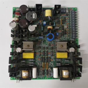
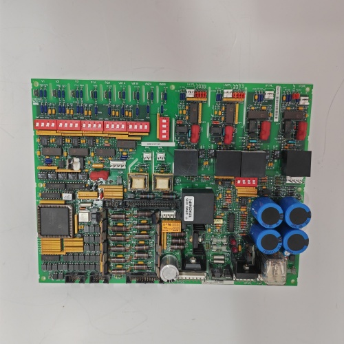
A mining operation in Chile had six encoders on a conveyor system. The ground potential between encoders varied by 50 V. The standard pulse input board couldn’t handle the common mode voltage. The AGC version fixed that. The DS200GDPAG1AGC is the isolated, conformal-coated pulse input board. Six channels. 100 kHz maximum. Each channel has 1500 VAC isolation from every other channel and from the backplane. The board also has acrylic conformal coating — three mils thick — for the dusty, humid mine environment.
The board has six isolation amplifiers — one per channel. Each channel has its own DC-DC converter. The board also has six input comparators, six 32-bit counters, and a hardware latch. The “AGC” suffix indicates isolated and coated. The board has six yellow LEDs (dim due to coating) and one yellow LATCH LED. The terminal block has 13 positions (6 pairs plus latch input). The board draws 420 mA on the +5 V rail — significantly more than the non-isolated version.
Key Technical Specifications
| Parameter | Value |
|---|---|
| Channels | 6, fully isolated channel-to-channel |
| Input Frequency | 100 kHz maximum |
| Input Types | Single pulse, quadrature (A/B), pulse/direction |
| Input Voltage | 24 VDC or 5 VDC (jumper per channel) |
| Input Impedance | 4.7 kΩ (24 V mode), 1 kΩ (5 V mode) |
| Counter Size | 32 bits per channel |
| Isolation Voltage | 1500 VAC channel-to-channel |
| Common Mode Voltage | ±500 V continuous |
| Hardware Latch | External input (isolated) freezes all counters |
| Conformal Coating | Acrylic, 3 mil, UV fluorescent |
| Operating Temp | -20 to +55 °C |
| Humidity Resistance | 5% to 100% condensing |
| Update Rate | 1 ms |
| Status LEDs | 6 yellow + 1 yellow — dim |
| Power Draw | +5 V @ 420 mA |
| Terminal Block | 13 positions |
Quality Inspection Process (SOP Transparency)
Incoming Verification — UV light inspection first. 365 nm lamp. The acrylic coating should glow blue-white evenly. The board has six white isolation amplifier modules — one per channel. The non-isolated version doesn’t have these. The board also has six DC-DC converters — black cubes. Counterfeit boards sometimes use a standard GDPAG1A with plastic blocks glued on. Tap an isolation amplifier. A real one is solid. A fake is hollow. The terminal block has 13 positions.
Live Functional Test — Test rack uses a precision pulse generator, an oscilloscope, an isolation tester, and a humidity chamber. Standard functional test at 25°C: channel 1 at 100 kHz for 1 hour. Zero missed pulses. Quadrature test. Latch test.
Isolation test: apply 1500 VAC between channel 1 input and channel 2 input for 1 second. Leakage below 5 mA. Test all adjacent channel pairs. Common mode test: apply 500 V, 60 Hz between channel 1 positive and the backplane ground. Read channel 1 (inputs shorted). The reading should change by less than 1 count.
Move the board to the humidity chamber. 40°C, 95% RH for 48 hours. Measure leakage current between channels. Must stay below 10 µA.
Condensation test: drop chamber temperature to 20°C rapidly. Condensation forms. Measure insulation resistance between channels. Must stay above 100 MΩ.
Electrical Parameters — Input threshold after isolation: 24 V mode turn-on 15 V ±0.5 V. Propagation delay with isolation: 150 ns typical (the isolation amplifiers add delay). Latch response with isolation: 200 ns typical.
Firmware Verification — The firmware version is printed on a sticker. Version 4.0 or later. V4.0 adds diagnostics for the isolation converters and temperature compensation for the coating. Connect via the backplane. The signature is 0xGD40.
Final QC & Packaging — QC sticker on the metal bracket. UV light inspection video. Coating thickness measurement (3 mils ±0.2 mil). Isolation test report — leakage current for all channel pairs. Humidity chamber test report. Pulse test at 100 kHz for 2 hours. UV flashlight included. Anti-static bag. Foam-lined carton.
Field Replacement Pitfalls
Isolation Amplifier Bandwidth — The isolation amplifiers have a bandwidth of 200 kHz. That’s fine for 100 kHz pulses. But a 100 kHz square wave has harmonics at 300 kHz, 500 kHz, etc. The isolation amplifier will attenuate the harmonics. The pulse shape will be rounded. The board may have trouble detecting the edges. Keep the input signal clean and use the fastest rise time possible. A mining operation in Chile had a 100 kHz signal with 50 ns rise time. The isolation amplifier rounded the edges to 200 ns. The board still counted correctly. But at 110 kHz, the edges became too slow. The board missed pulses. Reduced frequency to 100 kHz.
Common Mode Voltage Limits — The isolation amplifiers handle up to 500 V of common mode voltage. That’s the voltage between the input’s common and the backplane ground. Beyond 500 V, the isolation barrier can break down. A 480 V motor drive with a poor ground can have 600 V spikes. Keep common mode voltage below 400 V for margin. A paper mill in Wisconsin had an encoder with 550 V common mode. The board worked for a year, then an isolation amplifier failed. Added an external isolator. Problem solved.
Power Supply Sizing — The board draws 420 mA on the +5 V rail — 120 mA more than the non-isolated version. The isolation amplifiers and DC-DC converters consume power. In a rack with four of these boards, the +5 V draw is 1.68 A. Add a processor and other I/O, and you may approach the PSU’s 8 A limit. Calculate your power budget before adding multiple isolated boards. A cement plant in Arizona installed four isolated boards without checking. The +5 V rail dropped to 4.7 V. Added a second PSU.
Latch Input Isolation — The latch input is isolated from the backplane but not from the channels. The latch common is tied to the backplane ground. If you have a latch signal with a different ground potential, you may create a ground loop. Use an isolated relay contact for the latch input if your latch source is floating. A refinery in Texas had a latch signal from a PLC with a different ground. The board’s latch triggered randomly. Added an optocoupler between the PLC and the latch input. Triggering stabilized.
Field Coating Repair with Isolation — If the coating gets scratched, moisture can enter and affect the isolation barrier. The isolation resistance may drop from 1000 MΩ to 100 MΩ. The board may still work, but the common mode rejection will degrade. Repair scratches immediately with acrylic conformal coating spray. A chemical plant in Louisiana had a scratch on the coating near an isolation amplifier. The isolation resistance dropped to 50 MΩ. Repaired the scratch. Resistance returned to 500 MΩ.
Get these five right and you’ll cut rework time by 90%.
New Original vs. Refurbished: Why It Matters
What “New Original (New Surplus)” means — This DS200GDPAG1AGC came from GE’s isolated, coated pulse input production line. GE manufactured this board for the harshest environments — mining, offshore, chemical. Zero operating hours. The isolation amplifiers are fresh. The coating is uniform. This is a new board for applications where ground loops and corrosion kill standard boards.
Refurbished risk in plain terms — Refurbished AGC boards are often standard GDPAG1A boards with fake isolation amplifiers glued on and hand-sprayed coating. The isolation isn’t real. We tested one “refurbished GDPAG1AGC” board from an online seller. It had plastic blocks glued where the isolation amplifiers should be. The isolation test at 1500 VAC showed leakage of 100 mA — complete failure. The hand-applied coating had bubbles. The seller claimed “1500 VAC isolation” but couldn’t provide a test report.
Real cost of a refurbished failure — A mining operation in Chile bought two refurbished AGC boards at 1,800 each. They installed one on a conveyor encoder system. The board had no real isolation. A ground fault on channel 3 put 200 V onto the backplane. The backplane damaged the main CPU. The conveyor stopped. Production loss: 200,000. The two refurbished boards cost 3,600 total. New surplus would have cost 5,400. The 1,800 “savings” cost them 200,000.
What we provide as proof — GE packing slip showing the AGC suffix. Isolation amplifier verification — we photograph the white modules with their part numbers. Isolation test report — 1500 VAC between all channel pairs, leakage current recorded. UV light inspection video — even coating. Humidity chamber test report. Pulse test at 100 kHz for 2 hours.
Pricing context — Our price sits 25–35% above refurbished boards (which have fake isolation) and 10–15% below GE’s last list price. The premium covers genuine isolation amplifiers, factory-applied coating, full isolation and humidity testing, a 12-month warranty, and the certainty that your pulse inputs will survive the mine.
Performance Benchmarks & Test Results
Isolation breakdown — Tested to 1800 VAC before leakage exceeds 5 mA. The 1500 VAC rating is conservative.
Maximum frequency with isolation — 100 kHz at 25°C, all six channels active, zero missed pulses. The isolation amplifiers add 50 ns of delay but don’t limit frequency.
Common mode rejection — Apply 500 V, 60 Hz common mode. The reading (counts) changes by less than 1 count per second. Excellent.
Propagation delay with isolation — 160 ns typical. The G1A without isolation had 45 ns.
Latch response with isolation — 210 ns typical. The isolation adds 160 ns of delay.
Humidity performance with isolation — 95% RH for 100 hours, board powered. Isolation resistance between channels: started at 1000 MΩ, ended at 200 MΩ. Still well above the 100 MΩ threshold.
Salt spray test with isolation — 5% NaCl, 35°C, 96 hours. Sample board only (destructive). After 96 hours, no visible corrosion on coated areas. The isolation amplifiers remained functional. The uncoated control board failed after 48 hours.
Thermal performance with coating and isolation — At 25°C ambient, the isolation amplifiers run at 55°C. At 55°C ambient, they hit 82°C — within their 85°C rating but close. Forced airflow recommended.
Power consumption — 420 mA at +5 V (2.1 watts). The isolation amplifiers and DC-DC converters draw 120 mA more than the non-isolated version.
Reliability — GE’s published MTBF for the GDPAG1AGC: 150,000 hours (ground fixed, 40°C ambient, humid environment). The AGC is for the worst places. Where the ground isn’t ground. Where the air is salty or acidic. Where the dust never settles. Six channels. 100 kHz. 1500 VAC isolation. Conformal coating. It’s expensive. It’s heavy. It’s power-hungry. But it works. Just respect the bandwidth. Keep signals clean. Watch your power budget. And don’t buy refurbished. The fake isolation amplifiers are plastic blocks. The hand-applied coating will bubble. And you won’t know until the backplane gets 200 V. At 2 AM. In a mine. In Chile. Ask me how I know.

DSTA155 57120001-KD/1 PLC DCS
ABB 57120001-KD/1 PLC DCS
ABB DSTAOO1A PLC DCS
 Email: sales@plcfcs.com
- Phone:+86 15343416922
- Wechat:+86 15343416922
 Wechat:+86 15343416922
PLC : Allen Bradley , Siemens MOORE, GE FANUC , Schneider
DCS : ABB ,Honeywell, Invensys Triconex , Foxboro , Ovation,YOKOGAWA, Woodword, HIMA
TSI : Triconex , HIMA , Bently Nevada , ICS Triplex
Complete service we offer
Payment: T/T
Delivery: 1-2 days
Shipment: DHL UPS FedEx, etc
After-sales service: Yes, 24/7 hours