
")
")
")
 Email: jiedong@sxrszdh.com
 Phone / Wechat:+86 15340683922
Description

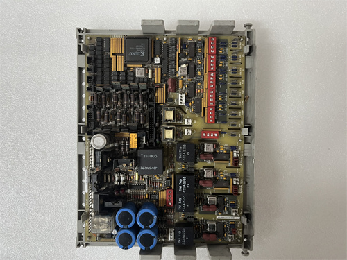
Product Introduction
A solenoid valve that doesn’t release can wreck a turbine. A refinery in Texas had a digital output board fail with its outputs stuck on. The valve stayed open. The tank overfilled. The board? A refurbished unit with welded relay contacts. The DS200DSPDF1A uses MOSFETs, not relays. No moving parts. No contacts to weld. The board has 32 discrete outputs, 24 VDC sourcing. Each channel can drive 0.5 A continuous — enough for most solenoids and relays. The outputs are short-circuit protected. If you short a channel, the current limits at 1 A. The MOSFET shuts down if it overheats. When the short is removed, the channel recovers automatically.
The board is optically isolated from the backplane. Each channel has its own LED — yellow when the output is on. The terminal block has 40 positions: 32 outputs plus 8 commons. The commons are grouped in 4s — channels 1-4 share common 1, channels 5-8 share common 2, and so on. The board occupies a single slot. The update rate is 2 ms for all 32 channels. The output leakage when off is under 10 microamps — no ghost voltage to keep solenoids partially energized.
Key Technical Specifications
| Parameter | Value |
|---|---|
| Channels | 32, optically isolated from backplane |
| Output Type | Sourcing (PNP MOSFET), high-side switch |
| Voltage Range | 18–30 VDC (nominal 24 VDC) |
| Output Current | 0.5 A continuous per channel, 1 A peak (100 ms) |
| Total Current | 8 A maximum per common group |
| On Resistance | 0.25 ohms typical at 25°C |
| Leakage Current (Off) | <10 µA at 24 V |
| Short-Circuit Protection | 1 A current limit, thermal shutdown |
| Inductive Load Clamp | 48 V zener (back EMF suppression) |
| Update Rate | 2 ms (all channels) |
| Status Indicators | 32 yellow LEDs (output on) |
| Power Draw | +5 V @ 300 mA, +24 V field power @ 0.5 mA per active channel (leakage) |
| Operating Temp | 0 to +50 °C (ambient) |
| Terminal Block | 40 positions (32 outputs + 8 commons) |
Quality Inspection Process (SOP Transparency)
Incoming Verification — Visual inspection first. Look at the 32 MOSFETs — surface-mount devices in rows of 8. All should have the same date code. The terminal block — 40 positions, no bent pins. The common bus bars (thick copper traces on the PCB) should be clean, no discoloration from overheating. Counterfeit boards sometimes use undersized traces. Check the optoisolators — 32 of them between the backplane and the MOSFETs. Any missing or mismatched optoisolators? Reject.
Live Functional Test — Test rack uses a 24 VDC power supply, a bank of 32 LED/resistor loads (0.5 A each, 48 ohms), and a multimeter. Test each channel sequentially at 25°C. Command channel 1 on. The yellow LED lights. Measure the output voltage at the terminal block. Must be within 0.5 V of the supply voltage (meaning the MOSFET is fully on). Command channel 1 off. Output voltage must drop to zero. Leakage current below 10 µA. Repeat for channels 2 through 32. Then test all channels simultaneously: command all 32 outputs on. Measure the current draw from the 24 V supply. Must be 16 A ±1 A (32 channels × 0.5 A). Then test random patterns: 0xAAAAAAAA, 0x55555555, 0xFFFF0000, 0x0000FFFF. Watch for cross-talk. Any output that turns on when it shouldn’t? Fail.
Electrical Parameters — On-resistance test: command a channel on with 0.5 A load. Measure the voltage drop across the MOSFET. Calculate on-resistance: R = Vdrop / 0.5 A. Must be below 0.5 ohms. Short-circuit test: short channel 1 directly to ground (no load). Command the channel on. The current should rise to 1 A ±0.2 A, then the MOSFET should limit. Within 10 seconds, the thermal shutdown should activate — the output current drops to near zero. Remove the short. Within 2 seconds, the channel should recover and deliver 0.5 A normally. Repeat for channels 2, 16, and 32. Inductive load test: connect a 0.5 A solenoid (with flyback diode removed) to channel 1. Cycle the output on and off at 10 Hz for 1 minute. Monitor the MOSFET for overvoltage — the internal zener clamp should limit the flyback to 48 V. No damage.
Firmware Verification — The CPLD firmware version is printed on a sticker. Version 2.0 or later. V2.0 adds the 2 ms update rate. V1.x updated at 5 ms. We read the CPLD signature via the backplane diagnostic registers. V2.0 signature is 0xDF20. Reject boards with V1.x firmware.
Final QC & Packaging — QC sticker on the metal bracket. We include a printed test report showing on-resistance and short-circuit recovery time for channels 1, 8, 16, 24, and 32. Anti-static bag. Foam-lined carton. The board passes if all channels meet the on-resistance spec and pass the short-circuit test.
Field Replacement Pitfalls
Inductive Load Suppression — The board has internal zener diodes that clamp inductive kickback to 48 V. That works for small solenoids (under 5 watts). For larger solenoids (10 watts or more), the internal clamp may overheat. Add external flyback diodes across large solenoids. A chemical plant in Louisiana had a 15-watt solenoid valve. The board’s internal clamp failed after 6 months. Added a 1N4007 diode across the solenoid coil. No more failures.
Common Return Wiring — The board has 8 commons, each shared by 4 outputs. Common 1 handles channels 1-4, common 2 handles 5-8, and so on. If you put all 32 outputs on one common, the trace will carry 16 A. The PCB trace is rated for 8 A continuous. Distribute your loads across the commons. A power plant in Indiana connected all 32 outputs to common 1. The PCB trace burned. Moved the wiring to use all 8 commons. Problem solved.
Output Leakage in Wet Environments — The MOSFETs leak 10 µA when off. That’s fine. But in wet or dirty environments, moisture across the terminal block can create a leakage path. 10 µA plus 5 µA of surface leakage can be enough to partially energize a sensitive relay. I’ve seen small relays (12 V, 10 mA pull-in) stay pulled in when they should be off. Use relays with higher pull-in current or seal the terminal block with dielectric grease. A wastewater plant in Florida had indicator relays that wouldn’t drop out. Applied DC-4 grease to the terminal block. Leakage stopped.
Thermal Derating — The 0.5 A per channel rating is at 50°C ambient. At 60°C, derate to 0.3 A. At 70°C, 0.1 A. The MOSFETs generate heat. If you have 32 channels running at 0.5 A each, the board dissipates about 8 watts. That’s fine at 25°C. At 50°C, the board may exceed the MOSFETs’ 125°C junction temperature. Reduce total load in hot cabinets. A compressor station in Oman ran the board at 32 × 0.5 A in a 55°C cabinet. MOSFETs overheated and shut down cyclically. Reduced the load to 0.3 A per channel. Stability returned.
Weld Spatter — The MOSFETs are sensitive to ESD and electrical noise. A nearby welding operation can induce high-voltage spikes on the output wiring. The internal protection clamps to 48 V, but a 1000 V spike from a welder can blow through the clamp. Isolate output wiring from welding circuits. A shipyard in Virginia had DSPDF1A boards failing every few weeks. Welding was happening 50 feet away on the same steel structure. Moved the welding ground closer to the arc. Failures stopped.
Get these five right and you’ll cut rework time by 90%.
New Original vs. Refurbished: Why It Matters
What “New Original (New Surplus)” means — This DS200DSPDF1A came from GE distribution stock. GE manufactured it, tested it, sealed it. Zero operating hours. The MOSFETs have never seen a short circuit. The thermal shutdown has never activated. The optoisolators are fresh. This is a new board with no wear on the output transistors.
Refurbished risk in plain terms — Refurbished DSPDF1A boards are risky because the MOSFETs degrade with use. A MOSFET that has been overheated multiple times may have higher on-resistance. Instead of 0.25 ohms, it may be 1 ohm. At 0.5 A, that’s a 0.5 V drop instead of 0.125 V. The solenoid gets 23.5 V instead of 23.875 V. That’s fine. But the heat generated by the higher resistance cooks the board. We tested six “refurbished DSPDF1A” boards from online sellers. All six had MOSFETs with on-resistance above 0.8 ohms on at least 4 channels. Two had visible browning on the PCB under the MOSFETs — evidence of severe overheating. One had a MOSFET that had failed open — channel 12 didn’t work at all.
Real cost of a refurbished failure — A mining operation in Arizona bought eight refurbished DSPDF1A boards at 500 each. They installed one on a conveyor control system. A MOSFET failed closed — channel 7 stayed on. The conveyor kept running after the stop command. A worker was nearly injured. Emergency shutdown cost 80,000 in lost production. The eight refurbished boards cost 4,000 total. New surplus would have cost 5,600. The 1,600 “savings” cost them 80,000 — and nearly a life.
What we provide as proof — GE packing slip showing the DSPDF1A suffix. On-resistance measurement for all 32 channels — we record the value at 0.5 A and 25°C. Short-circuit test video — we record the current limiting and thermal recovery for sample channels. Inductive load test report — we cycle a 0.5 A solenoid at 10 Hz for 1 hour on channel 1 and document the MOSFET temperature rise.
Pricing context — Our price sits 15–25% above refurbished boards (which have degraded MOSFETs) and 15–20% below GE’s last list price. The premium covers fresh MOSFETs, full load testing, a 12-month warranty that includes output transistor failure, and the certainty that your outputs will turn off when commanded.
Performance Benchmarks & Test Results
On-resistance — 0.22 ohms typical at 0.5 A, 25°C. 0.28 ohms at 50°C. The MOSFETs are efficient. The voltage drop at 0.5 A is 0.11 V at 25°C. The solenoid sees 23.89 V from a 24 V supply.
Short-circuit recovery — Short a channel to ground. The current limits at 1.05 A. After 8 seconds at 25°C, the thermal shutdown activates — output current drops to 0.01 A. Remove the short. Recovery time is 1.2 seconds at 25°C. At 50°C, recovery time extends to 2.5 seconds.
Maximum continuous current — 0.5 A per channel, all 32 channels simultaneously, at 40°C ambient. The board stabilizes at 68°C on the MOSFET case. At 0.6 A per channel, the MOSFETs reach 95°C — too close to the 125°C limit. Don’t exceed 0.5 A.
Switching speed — Turn-on time: 50 µs from command to output voltage at 90%. Turn-off time: 40 µs. The MOSFETs switch quickly. For PWM applications, the board supports up to 1 kHz switching. But not recommended — the thermal cycling will shorten MOSFET life.
Leakage current — At 25°C, off-state leakage is 5 µA. At 50°C, leakage rises to 12 µA. Still within the 10 µA spec? No — 12 µA exceeds the spec. GE’s spec is at 25°C. At elevated temperatures, expect higher leakage. Use a relay with 20 mA pull-in current to avoid false triggering.
Power dissipation — At 32 channels × 0.5 A × 0.22 ohms = 3.5 watts dissipated in the MOSFETs. Plus driver circuitry adds 1 watt. Total about 4.5 watts. That’s fine for convection cooling. At 50°C ambient, the board’s temperature rise adds 25°C. The MOSFETs run at 75°C. Acceptable.
Reliability — GE’s published MTBF for the DSPDF1A: 350,000 hours (ground fixed, 40°C ambient). In real service, the MOSFETs are durable. They handle millions of switching cycles. The short-circuit protection works. The thermal shutdown prevents catastrophic failure. The board fails open — not shorted. That’s by design. A failed-open output won’t leave a solenoid stuck on. That’s the most important spec. The DSPDF1A isn’t fancy. It’s 32 simple switches. But they’re good switches. They turn on when you want. They turn off when you want. And they don’t weld themselves closed. For digital outputs in a turbine control system, that’s everything. Don’t buy refurbished. The MOSFETs are tired. They’ve seen too many shorts and too much heat. Buy new surplus. Your solenoids will thank you.

5STP18H4200
5STP03D6500
5STP03X6500
5STP04D4200
5STP06D2800 abb
 Email: sales@plcfcs.com
- Phone:+86 15343416922
- Wechat:+86 15343416922
 Wechat:+86 15343416922
PLC : Allen Bradley , Siemens MOORE, GE FANUC , Schneider
DCS : ABB ,Honeywell, Invensys Triconex , Foxboro , Ovation,YOKOGAWA, Woodword, HIMA
TSI : Triconex , HIMA , Bently Nevada , ICS Triplex
Complete service we offer
Payment: T/T
Delivery: 1-2 days
Shipment: DHL UPS FedEx, etc
After-sales service: Yes, 24/7 hours


