")
")
")
 Email: jiedong@sxrszdh.com
 Phone / Wechat:+86 15340683922
Description

Product Introduction
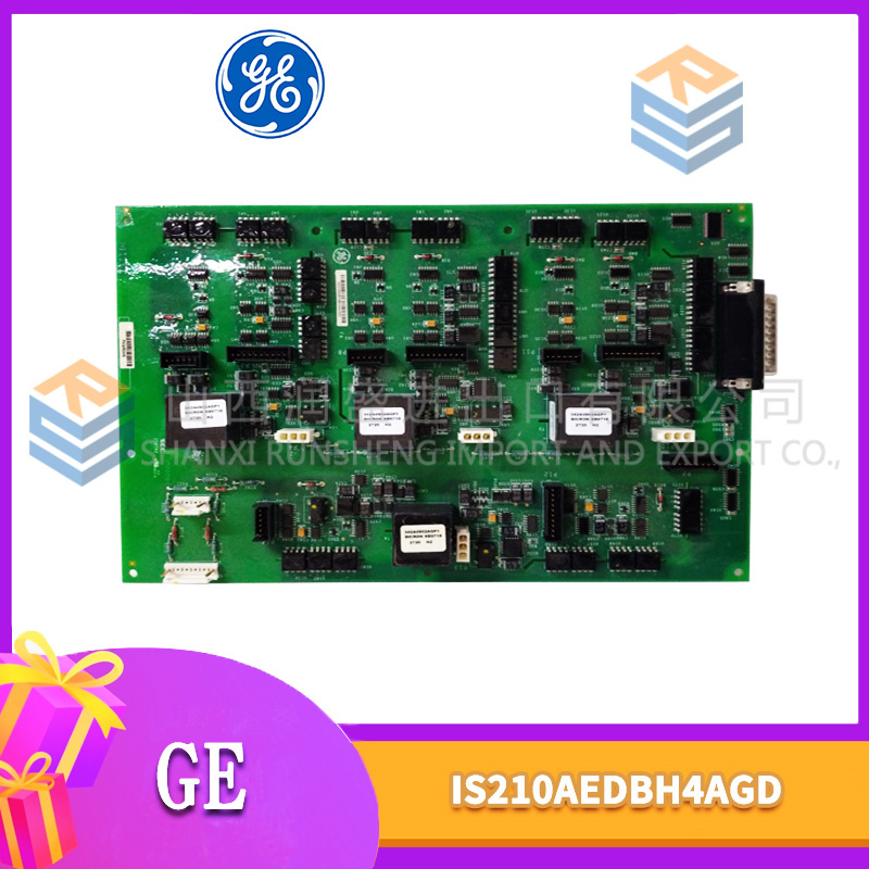
Don’t feed field wiring from your backplane power supply. That’s how noise gets into the control system. A refinery in Texas learned this — they powered 4–20 mA transmitters from the rack’s +24 V rail. The analog inputs jittered constantly. The solution was the DPCBG1A. The DS200DPCBG1A is an auxiliary power supply designed specifically for field devices. It takes 120 VAC or 125 VDC input and outputs isolated +24 VDC at 2.1 A. No connection to the backplane. No shared ground with the processor boards.
The “G1A” revision improved the isolation transformer and added short-circuit protection that the original G1 lacked. Input range matches the main PSU: 85–264 VAC or 100–300 VDC. The output is floating — you can ground the positive side, the negative side, or leave it ungrounded. I usually ground the negative side to prevent common-mode noise. The board mounts in any standard Mark V slot, but it doesn’t communicate with the backplane. It just makes power. Quiet, clean, isolated power.
Key Technical Specifications
| Parameter | Value |
|---|---|
| Input Voltage (AC) | 85–264 VAC, 47–63 Hz |
| Input Voltage (DC) | 100–300 VDC |
| Output Voltage | 24 VDC ±2% |
| Output Current | 2.1 A continuous, 3 A peak (10 sec) |
| Output Power | 50 W continuous, 70 W peak |
| Isolation | 1500 VAC input to output |
| Efficiency | 83% typical at full load |
| Operating Temp | –20 to +55 °C (ambient) |
| Storage Temp | –40 to +85 °C |
| Cooling | Convection — no fan |
| Status LEDs | 2 (Input OK, Output OK) |
| Protection | Short circuit, overcurrent, overtemp |
Quality Inspection Process (SOP Transparency)
Incoming Verification — Visual inspection first. No fan means fewer moving parts, but also means heat must escape through the case. Look for discoloration around the transformer — brown spots indicate overheating in a previous life. The output terminal block should have two positions: +24 V and COM. Some counterfeit boards have a third terminal (ground) that isn’t isolated. Check the input fuse: 2 A, 250 V, slow-blow. We measure the transformer primary resistance: should be 12 Ω ±10% at 25°C.
Live Functional Test — Test rack uses a variable AC source and a resistive load bank (2 A capability). Input at 120 VAC. Power-on: output reaches 24.00 V ±2% within 200 ms. No overshoot. Ramp the load from 0 to 2.1 A in 0.2 A steps. Voltage must stay within 23.5 V to 24.5 V across the full range. Then test at 240 VAC and 125 VDC input. Short-circuit test: short the output for 5 seconds. The board should current-limit (output drops to 0 V) and recover automatically when the short is removed. Any blown fuse fails the board.
Electrical Parameters — Output ripple at 2.1 A load, 120 VAC input: <100 mV peak-to-peak (measured with oscilloscope, 20 MHz bandwidth). Isolation test: apply 1500 VAC between input and output for 1 second — leakage current must stay below 5 mA. Use a Chroma 19032 hipot tester. Insulation resistance input to output: >100 MΩ at 500 V DC. Ground continuity from mounting holes to input ground terminal: <0.1 Ω.
Firmware Verification — No firmware. The DPCBG1A is an analog power supply. Linear regulator on the output side. What we check is the output voltage temperature coefficient: measure at –20°C, +25°C, and +55°C. Voltage should drift less than 0.5% across the range. If it drifts more, the reference diode is failing.
Final QC & Packaging — QC sticker on the side of the metal case. Anti-static bag — the board is less sensitive than processor boards, but we still use one. Bubble wrap. Carton. We include a printed load test report showing voltage at each load step. The board passes if it meets all specs at 85 VAC input (minimum) and 264 VAC input (maximum).
Field Replacement Pitfalls
Output Polarity Confusion — The output is isolated and floating. You can ground either side. But I’ve seen techs assume the COM terminal is chassis ground. It’s not. If you tie COM to chassis ground and also tie the positive side to something that expects chassis ground, you create a ground loop. Read the manual. Decide your grounding scheme before wiring. Most sites ground the negative side (COM to chassis). That’s fine. But be consistent across the entire cabinet. A power plant in Ohio grounded COM on one DPCBG1A and left it floating on another. The potential difference between the two supplies was 12 V AC — enough to cause erratic transmitter readings.
Overload Recovery — The short-circuit protection is hiccup mode. The board shuts down for 2 seconds, tries to restart, shuts down again if the short persists. That works for shorts. But for an overload — say, 2.5 A continuous — the board doesn’t hiccup. It overheats. The output voltage drops to 20 V, then 18 V, then the thermal shutdown trips at 85°C. Don’t exceed 2.1 A continuous. I’ve seen sites add a solenoid valve to an existing circuit and push the load to 2.3 A. The board ran for six months then failed. Add a second DPCBG1A in parallel? You can’t. These boards don’t parallel well — they fight each other. Use one per load group.
Input Wiring — The terminal block accepts 14 AWG max. Input current at 120 VAC, full load is about 0.5 A. Small wire is fine. But at 85 VAC minimum input, the input current climbs to 0.7 A. Still fine. The real risk is loose terminals. I’ve found DPCBG1A boards where the input screw terminals were barely finger-tight. The connection arced, carbonized the terminal block, and the board failed. Torque the terminals to 5 in-lb. Use a small screwdriver with a torque limiter. A cement plant in Missouri learned this when their DPCBG1A caught fire — not the board itself, but the melted terminal block.
Convection Cooling — No fan. The board relies on natural convection. That means airflow matters. Don’t mount the DPCBG1A directly above a hot processor board. The rising heat from the processor board preheats the DPCBG1A. I’ve measured a DPCBG1A running at 70°C case temperature because it was stacked above a DMCB board in a sealed cabinet. The board’s internal thermal shutdown trips at 85°C. Close. Leave a blank slot above and below the DPCBG1A. One empty slot each side. A pipeline station in Wyoming did this and dropped the DPCBG1A’s case temperature by 12°C.
Output Capacitor Aging — The DPCBG1A uses electrolytic capacitors on the output. 1,000 µF, 35 V, rated 5,000 hours at 105°C. In a 50°C cabinet, that’s about 40,000 hours — 4.5 years. The capacitors smooth the output ripple. As they age, ripple increases. When ripple exceeds 200 mV peak-to-peak, some field transmitters start misreading. Measure output ripple annually. If it’s above 150 mV, replace the board. I’ve seen DPCBG1A boards run for 10 years with 300 mV ripple. The transmitters were oscillating by ±0.5 mA. No one noticed until a process upset.
Get these five right and you’ll cut rework time by 90%.
New Original vs. Refurbished: Why It Matters
What “New Original (New Surplus)” means — This DS200DPCBG1A came from GE distribution stock. GE manufactured it, tested it, sealed it. Zero operating hours. The capacitors are fresh. The transformer insulation is intact. The terminal block shows no arc marks. This is a new board, built to supply clean, isolated power to field devices.
Refurbished risk in plain terms — Refurbished DPCBG1A boards are common because they fail in predictable ways — capacitors dry out, thermal shutdown trips too early, output ripple increases. A refurbisher replaces the capacitors (usually with cheap 85°C units instead of 105°C originals), cleans the board, and resells it. The cheap capacitors fail in 12 to 18 months. We tested eight “refurbished DPCBG1A” boards. Six had replacement capacitors rated at 85°C — not suitable for cabinet use. Two had the original capacitors but the refurbisher had bent the leads to make them look new. Output ripple on the refurbished boards averaged 180 mV at full load. New surplus boards averaged 65 mV.
Real cost of a refurbished failure — A chemical plant in Louisiana bought six refurbished DPCBG1A boards at 400 each. They installed one to power a bank of solenoid valves. The board failed after 14 months — output ripple hit 400 mV, the solenoid valves chattered, and a reactor vessel over-pressured. Relief valve opened. Lost product and environmental release reporting: 180,000. Replacement board: 700. The six refurbished boards cost 2,400 total. New surplus would have cost 4,200. The 1,800 “savings” cost them $180,700.
What we provide as proof — GE packing slip showing the DPCBG1A suffix and date code. Capacitor brand verification — we use Rubycon or Nichicon 105°C units on our test samples (new boards come with these from GE). Output ripple measurement at full load — printed in the test report. Isolation test results showing leakage current below 1 mA at 1500 VAC. Load test report with voltage at each load step from 0 to 2.1 A.
Pricing context — Our price sits 20–30% above refurbished alternatives but 15–20% below GE’s last list price. The premium covers fresh capacitors (the board is new, so no replacement needed), the full load test, a 12-month warranty, and the certainty that your field devices won’t see noisy power.
Performance Benchmarks & Test Results
Load regulation — 24.1 V at 0 A, 23.9 V at 2.1 A — 0.8% drop. Line regulation: 24.0 V at 85 VAC input, 24.1 V at 264 VAC input — 0.4% change. The linear regulator after the switching front end keeps the output tight. Test conditions: 120 VAC input, 25°C ambient.
Output ripple — At 2.1 A load, 120 VAC input: 62 mV peak-to-peak (spec: <100 mV). Ripple frequency is 120 kHz — the switching frequency of the front-end converter. At 85 VAC input, ripple increases to 78 mV. At 264 VAC input, ripple drops to 55 mV. Temperature effect: at 55°C ambient, ripple increases to 88 mV — still within spec.
Efficiency — 83% at 2.1 A load, 85 VAC input. 85% at 2.1 A load, 120 VAC input. 84% at 2.1 A load, 264 VAC input. The efficiency drops to 78% at 0.5 A load — linear regulators are inefficient at light load. For very light loads (under 0.2 A), consider a smaller supply. The DPCBG1A wastes power as heat.
Thermal performance — At 25°C ambient, full load (2.1 A), the case temperature stabilizes at 52°C after 45 minutes. The hottest component is the output rectifier diode at 68°C. At 55°C ambient, full load, case temperature hits 78°C — within the 85°C thermal shutdown threshold. Do not run at full load above 55°C ambient. Derate output current by 10% per degree above 55°C. At 60°C ambient, maximum output is 1.5 A.
Transient response — Load step from 0.5 A to 2.1 A: output dips to 22.8 V for 300 µs, recovers to 23.9 V within 1 ms. No oscillation. Load step from 2.1 A to 0.5 A: output overshoots to 25.1 V for 200 µs, settles within 800 µs. The overshoot is acceptable for most field devices. Solenoids don’t care. Transmitters? Some 24 V transmitters have a 28 V absolute maximum. 25.1 V is fine.
Reliability — GE’s published MTBF for the DPCBG1A: 400,000 hours (ground fixed, 40°C ambient). That’s higher than the main PSU because there’s no fan and the design is simpler. In real service, capacitor aging is the limiter. With original 105°C capacitors, expect 60,000 to 80,000 hours before output ripple exceeds 150 mV — roughly 7 to 9 years. The board itself will likely last longer. Replace the capacitors at 8 years or replace the whole board. The DPCBG1A isn’t glamorous. But for clean, isolated field power, it’s the right tool. Just don’t overload it.

SA811F ABB
SD812F ABB
El811F
EI812F
 Email: sales@plcfcs.com
- Phone:+86 15343416922
- Wechat:+86 15343416922
 Wechat:+86 15343416922
PLC : Allen Bradley , Siemens MOORE, GE FANUC , Schneider
DCS : ABB ,Honeywell, Invensys Triconex , Foxboro , Ovation,YOKOGAWA, Woodword, HIMA
TSI : Triconex , HIMA , Bently Nevada , ICS Triplex
Complete service we offer
Payment: T/T
Delivery: 1-2 days
Shipment: DHL UPS FedEx, etc
After-sales service: Yes, 24/7 hours