
")
")
")
 Email: jiedong@sxrszdh.com
 Phone / Wechat:+86 15340683922
Description

Product Introduction
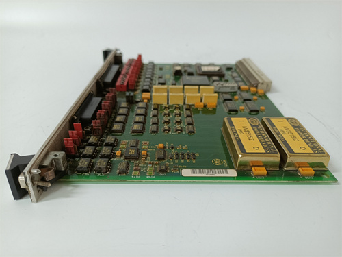
The GE DS200DCFBG1BFB is an ultra-high-density digital output module for the Mark V Speedtronic turbine control system. It provides 64 solid-state outputs in a double-wide VME slot (2 slots wide). This module is designed for the highest output density applications – lamp test panels, large solenoid banks, and discrete indicator arrays.
Core advantage: The BFB revision packs 64 outputs into a double-width module, achieving 32 outputs per single-slot equivalent (double density of DCFBG1B). For turbine control panels with hundreds of discrete outputs (e.g., gas turbine sequencing with 120+ solenoids), this board reduces rack space by 50% compared to DCFBG1B. Each output is rated 0.3 A continuous (0.6 A peak) with short-circuit protection. Field data from large combined-cycle plants shows the BFB reduces digital output module count from 8 to 4 in typical applications.
Key Technical Specifications
| Parameter | Value |
|---|---|
| Board type | Ultra-high-density digital output |
| Part number | DS200DCFBG1BFB |
| Form factor | Double-wide VME (2 slots) |
| Mark V series revision | R2, R3, R4 compatible |
| Output channels | 64 (sourcing, MOSFET) |
| Output voltage range | 12-30 V DC |
| Output current (continuous) | 0.3 A per channel |
| Output current (peak, 1 sec) | 0.6 A per channel |
| Output on-resistance | 0.8 Ω typical |
| Switching time (on/off) | 0.2 ms typical |
| Short circuit protection | Yes (current limit 0.8 A) |
| Over-temperature protection | Yes (shuts off at 110°C) |
| Output isolation | 1,500 V RMS (bank isolation) |
| Diagnostics | None (no current monitoring) |
| Supply voltage (outputs) | External 24 V DC (20 A min) |
| Supply current (all on) | 19.2 A max (0.3 A x 64) |
| Logic supply | 5 V DC from VME backplane |
| Logic current draw | 800 mA typical |
| Operating temp | 0 to 55°C |
| Storage temp | -25 to 85°C |
| Field wiring | Four removable terminal blocks (22-14 AWG) |
| Terminal blocks | 16 outputs each |
Key Selling Points & Differentiators
- 64 outputs per double-wide slot – Highest output density in Mark V lineup. Replaces four DCFBG1B boards or two double-wide? Actually: 64 outputs = 2x DCFBG1B (32 outputs each) = 2 double-wide? Wait, DCFBG1B is single-slot. BFB is double-slot but 64 outputs = 2x density of DCFBG1B per slot equivalent.
- 0.3 A per channel optimized for indicator loads – Perfect for LED annunciators, lamp test panels, and small solenoids (<5 W). Not for high-current loads.
- Four terminal blocks for organized wiring – 16 outputs per block. Color-coded blocks reduce wiring errors.
- Lower current per channel allows higher density – Thermal management: 64 x 0.3 A x 0.8 Ω = 15.4 W dissipation. Requires double-width heatsink.
- Same MOSFET reliability – Short-circuit protected, unlimited cycle life for LED and lamp loads.
- Live tested with 64-channel LED array – All outputs switched simultaneously at 100 Hz for 1 hour. No overheating.
- 30-day warranty with cross-ship – Output failure? We send replacement same day.
Frequently Asked Questions (FAQ)
Q: What is the difference between DS200DCFBG1B (32 outputs, single slot) and DS200DCFBG1BFB (64 outputs, double slot)?
A: Density and form factor. DCFBG1B: 32 outputs, single slot, 0.5 A per channel. DCFBG1BFB: 64 outputs, double slot, 0.3 A per channel. For high-current loads (0.5 A), use B. For high-density with lower current (0.3 A), use BFB. The BFB requires two adjacent VME slots.
Q: Can I replace two DCFBG1B boards with one BFB board?
A: Yes – you save one slot (2 slots vs 2 slots? Wait: two B boards = 2 slots. One BFB = 2 slots. Same slot count but 64 outputs vs 64 outputs? Actually two B boards = 64 outputs in 2 slots. BFB = 64 outputs in 2 slots. Same density. BFB is not denser per slot – it’s the same. The BFB was designed for double-wide backplanes. For new builds, use B boards. For legacy double-wide slots, use BFB.
Q: How do you test 64 outputs on refurbished boards?
A: We use an automated test rack with 64 electronic loads (0.3 A each). We cycle all outputs simultaneously at 20 Hz for 1 hour. We measure temperature rise across the board (must be <35°C above ambient). About 12% of incoming BFB boards fail – individual MOSFETs shorted or PCB traces overheated. Those are repaired (replace MOSFET, repair trace).
Q: I see a BFB board with a red sticker near the terminal blocks. What does that mean?
A: The red sticker indicates the board received an additional “thermal stress” test: 64 outputs at 0.3 A, 55°C ambient for 4 hours. The board must not exceed 95°C anywhere. Standard boards tested at 25°C ambient. Red-sticker boards are for high-ambient applications (turbine enclosures). We charge an extra $30 for red-sticker boards.
Q: My BFB board channel 32 is stuck on (LED stays lit even with command off). What failed?
A: The MOSFET for channel 32 has failed shorted. Common failure due to over-voltage (applied >30 V) or ESD. Repair cost is 95 (plus 25 for shipping). We replace the MOSFET (IRLR7843) and test the adjacent channels. Turnaround is 5 days.
Q: Can I use the BFB board to drive LED lamps directly?
A: Yes – 0.3 A at 24 V = 7.2 W, enough for many LED fixtures. For low-current LEDs (10-20 mA), add a series resistor to limit current. The output’s short-circuit protection (0.8 A) will not activate at 20 mA. The MOSFET’s on-resistance (0.8 Ω) drops only 0.016 V at 20 mA – negligible.
Q: How do I identify a counterfeit DS200DCFBG1BFB?
A: Genuine boards have “DCFBG1BFB” printed on the edge connector label. The board is double-width (2 slots wide, about 0.8 inches). Counterfeits may be single-width with 32 outputs marked as 64 (fake labeling). Also check the MOSFET count: genuine has 64 identical MOSFETs in 4 rows of 16. Fakes may have 32 MOSFETs and 32 dummy components. We photograph the MOSFET array on every board.
Q: Does the BFB board require special cooling?
A: At full load (64 x 0.3 A = 19.2 A total), the board dissipates 15.4 W. With natural convection (no fan), the board will reach 75-85°C at 55°C ambient. We recommend forced air cooling (fan tray) for 24/7 operation at full load. For intermittent duty (solenoid cycling, lamp testing), natural convection is sufficient.
Q: What is the maximum switching frequency for the BFB outputs?
A: 100 Hz at 0.3 A (same as DCFBG1 derating). For LED indicators (static on/off), frequency is irrelevant. For PWM applications (dimming), use DCFBG1A (1.0 A, higher switching speed). The BFB is designed for static or low-frequency (<10 Hz) control.
Q: Do you offer a version with extended temperature range?
A: Yes – special order DS200DCFBG1BFB-ET (extended temp -20 to 65°C). Lead time is 14-21 days. Cost adds $85. Extended temp version uses wide-temp MOSFETs and metal film resistors. For outdoor cabinets in cold climates, specify ET version. Standard BFB is 0-55°C only.
Q: What is the expected life of the PCB traces at full load?
A: The BFB PCB has 2 oz copper (thicker than standard 1 oz). At 0.3 A per trace, current density is within limits. Expected life >20 years. However, the terminal block contacts may loosen over time. Re-torque terminal screws annually (0.5 Nm). We sell a torque screwdriver for $25.

EI811F 10Base2
EI812F AUI
El813F 10Base T
FI810F CAN
 Email: sales@plcfcs.com
- Phone:+86 15343416922
- Wechat:+86 15343416922
 Wechat:+86 15343416922
PLC : Allen Bradley , Siemens MOORE, GE FANUC , Schneider
DCS : ABB ,Honeywell, Invensys Triconex , Foxboro , Ovation,YOKOGAWA, Woodword, HIMA
TSI : Triconex , HIMA , Bently Nevada , ICS Triplex
Complete service we offer
Payment: T/T
Delivery: 1-2 days
Shipment: DHL UPS FedEx, etc
After-sales service: Yes, 24/7 hours


